Basic Service Documentation. Copyright General Electric Company.
Object ID: 00000018WIA30CAFF20GYZ
Topic ID: id_13106129 Version: 1.6
Date: Apr 17, 2020 3:00:00 AM
DCPS for ICE Replacement
Prerequisites
Table 1. Personnel requirements
Required persons
Preliminary requirements
Procedure
Finalization
1
Not Applicable
30 minutes
15 minutes
Table 2. Tools and test equipment
Item
Quantity
Effectivity
Part number
Manufacturer
Standard Tool
1
-
-
-
Table 3. Replacement parts
Item
Quantity
Effectivity
Part number
Manufacturer
DCPS for ICE
1
-
5725996
-
Table 4. Safety
Warning
ELECTROCUTION HAZARD!
DANGEROUS AND OR FATAL VOLTAGES ARE PRESENT IN THE ENERGIZED
CABINET.
Follow loto steps as given in first section of this document
to disable and verify safe voltage levels.
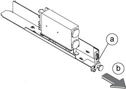
About this task
The DCPS for ICE is located beside the ICE. DCPS is an assembly of the power module with the mechanical frame.
Procedure
Notice
NEVER turn an ICN ON/OFF from the power button on the front. The ICNs have software running on disk drives that can be corrupted if not shut down properly.
Notice
Follow the procedure mentioned below for removing power to ICN chassis. Failure to properly power down an ICN can result in premature ICN failure.
From the Common Service Desktop, turn off the ICN(s). Refer
to ICN On/Off Procedure.
For the first 3 or 4 minutes, LEDs come on only at the
rear of the ICN, next to the power cables. After 3-4 minutes, you
will hear the ICN fans come on and then the LED at the front of the
ICN starts flashing.
Perform a TPS Reset and then run one head or body scan.