- id_2014696
- Version: 3.0
- Date: Dec 18, 2019 2:57:08 AM
Installing the Integrated Control Engine (ICE) fan assembly
Install the Integrated Control Engine (ICE) fan assembly in the System Cabinet.
Prerequisites
| Personnel requirements | |||
|---|---|---|---|
| Required persons | Preliminary requirements | Procedure | Finalization |
| 1 | - | 5 to 10 minutes | - |
| Tools and test equipment | |||
|---|---|---|---|
| Item | Quantity | Part number | Manufacturer |
| Nonmagnetic Titanium Service Tool Kit, Small Set | 1 Kit | 5113258 | - |
| Nonmagnetic Titanium Service Tool Kit, Large Set | 5112581 | - | |
| Replacement parts | |||
|---|---|---|---|
| Item | Quantity | Part number | Manufacturer |
| ICE Fan Assembly pICE fan | 2 | Refer to FRU Manual5485930 | - |
Procedure
- Do the following steps to install a fan in the back of the ICE.
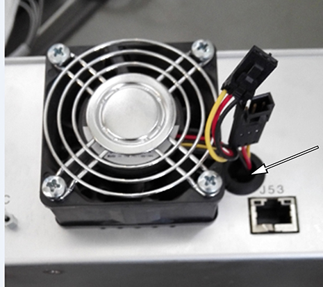
- Connect the fan cable to the power cable in the hole beside the fan slot.note: Be careful that the power cable does not fall into the hole.
Figure 1. Hole for power cable
- Tighten four screws to secure the fan to the ICE.
Figure 2. Installing the fan
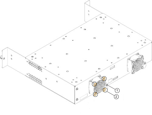
1 Connect the fan cable to the power cable 2 Tighten four screws - Connect the fan cable to the power cable in the hole beside the fan slot.
- Restore the ICE by reverse order.
Figure 3. Power plug near Ethernet bracket
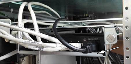
Figure 4. Cables next to the chassis
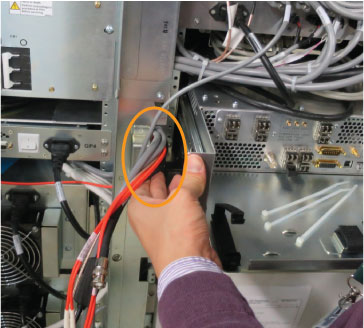 note: Restore the cables as shown below. J numbers in orange need to be reconnected.