- id_12374037
- Version: 1.5
- Date: Jan 17, 2020 11:00:10 AM
Leak Sensor Strip Replacement
Prerequisites
| Required persons | Preliminary requirements | Procedure | Finalization |
|---|---|---|---|
| 1 | Not Applicable | 40 minutes per tray | Not Applicable |
| Item | Quantity | Effectivity | Part number | Manufacturer |
|---|---|---|---|---|
| Standard Tool Kit | 1 | - | - | - |
| Item | Quantity | Effectivity | Part number | Manufacturer |
|---|---|---|---|---|
| Leak Sensor Strip Kit | 1 | - |
5266125 |
- |
Overview
This document covers replacing leak sensor strips on the following components:
-
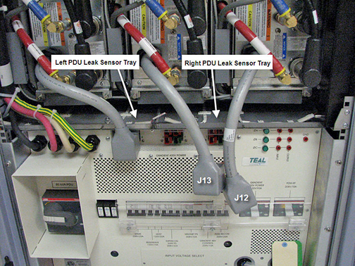
Right PDU leak sensor tray (Right PDU Leak Sensor Tray)
-
Left PDU leak sensor tray (Left PDU Leak Sensor Tray)
-
XGD leak sensor tray (PDU and XGD Leak Sensor Tray)
-
RF leak sensor tray (RF Leak Sensor Tray)
Right PDU Leak Sensor Tray
Removing Leak Sensor Strip
Procedure
- Perform LOTO on the PDU. See the MR Service Safety Manual, PN 5452735.
- Remove cables J12 and J13 from the PDU. This allows access to
the right PDU leak sensor tray.
Figure 1. Remove PDU Cables
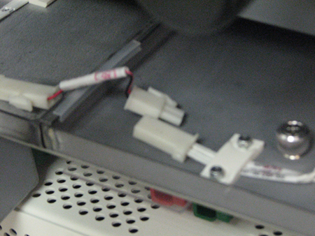
- Unplug the two leak sensor strip connectors on both sides of
the tray, using the white quick disconnect.
Figure 2. Unplug Leak Sensor Strip Connectors
- Loosen the two thumb screws on the top of the tray.
- Pull the tray out from the cabinet.
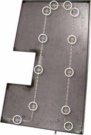
- Remove all 12 retainers holding the leak sensor strip to the
tray.
Figure 3. Remove 12 Retainers
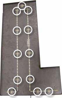 note:
note:The sensor is folded at the corners. This configuration will be repeated during installation of the new sensor strip.
- Remove the sensor strip.
Installing Leak Sensor Strip
Procedure
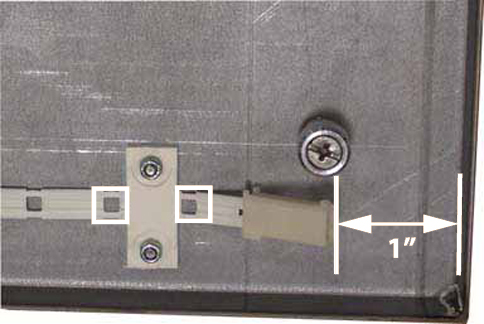
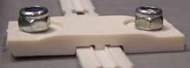
- Start routing the new leak sensor strip approximately 1 inch
from the right edge of the tray. Seat the strip so that the first
and second open wire holes fall on either side of the retainer.note:
When routing this leak sensor strip, it does not matter which end is used. The ends are interchangeable.
Figure 4. Properly Seated Leak Sensor Strip
Before tightening, be sure all retainers lay properly on top of the sensor strip with the retainer channels and sensor interlocking.
Figure 5. Properly Seated Retainer
- Tighten the nuts for each retainer.
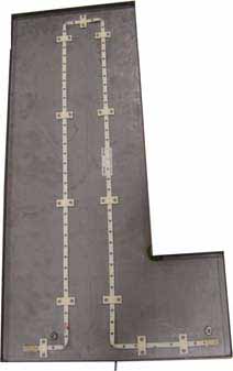
- Continue routing the sensor strip and retainers, making sure
that bends do not cause the open wire holes to cross each other.
Figure 6. Bending Leak Sensor Strip
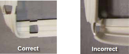
Figure 7. Fully Routed Leak Sensor Strip
- Slide the tray into the right side of the cabinet.
- Tighten the two thumb screws to secure the tray to the cabinet.
- Reconnect the leak sensor strip connectors on both sides of the tray.
- Reconnect cables J12 and J13 to the PDU.
Left PDU Leak Sensor Tray
This procedure takes 45 minutes from beginning to finalization.
Removing Leak Sensor Strip
Procedure
- Follow Step 1 through Step 5 to remove the right PDU leak sensor tray. This allows access to the left PDU leak sensor tray.
- Unplug the remaining leak sensor strip connector on the left PDU leak sensor tray.
- Remove the two thumb screws on the top of the tray.
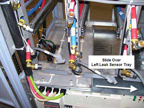
- Slide the left PDU leak sensor tray to the right in the cabinet
and pull it out.
Figure 8. Slide Over Left PDU Leak Sensor Tray
- Remove all 12 retainers holding the leak sensor strip to the
tray.
Figure 9. Remove 12 Retainers
 note:
note:The sensor is folded at the corners. This configuration will be repeated during installation of the new sensor strip.
- Remove the sensor strip.
Installing Leak Sensor Strip
Procedure
- Start routing the new leak sensor strip approximately 1 inch
from the right edge of the tray. Seat the strip so that the first
and second open wire holes fall on either side of the retainer. See Figure 4. note:
When routing this leak sensor strip, it does not matter which end is used. The ends are interchangeable.
Before tightening, be sure all retainers lay properly on top of the sensor strip with the retainer channels and sensor interlocking Figure 5.
- Tighten the nuts for each retainer.
- Continue routing the leak sensor strip and retainers, making
sure that bends do not cause the open wire holes to cross each other.
See Figure 6.
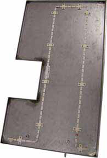
Figure 10. Fully Routed Leak Sensor Strip
- Push the left leak sensor tray into the right side of the cabinet and slide it to the left side. See Figure 8.
- Tighten the two thumb screws to secure the tray to the cabinet.
- Slide the right leak sensor tray into the right side of the cabinet.
- Tighten the two thumb screws to secure the tray to the cabinet.
- Reconnect the leak sensor strip connectors for both trays (4 connections total).
- Reconnect cables J12 and J13 to the PDU.
PDU and XGD Leak Sensor Tray
This procedure takes about 25 minutes from beginning to finalization.
Removing Leak Sensor Strip
Procedure
- Perform LOTO on the PDU. See the MR Service Safety Manual, PN 5452735.
- Unplug the leak sensor strip connectors on the left side of the tray.
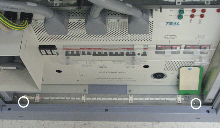
- Remove the two screws holding the XGD leak sensor tray to the
base of the cabinet.
Figure 11. Remove XGD Leak Sensor Tray Screws
- Remove the tray from the cabinet.
- Remove the four retainers holding the leak sensor strip to the tray.
Installing Leak Sensor Strip
Procedure
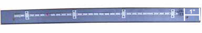
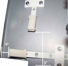
- Start routing the new leak sensor strip approximately 3 inches
from the right edge of the tray, with the grey connector to the right
side. Seat the strip so that the first and second open wire holes
fall on either side of the retainer.
Figure 12. Routing Leak Sensor Strip
Be sure the retainer lays properly on top of the sensor strip before tightening. See Figure 5.
- Tighten the nuts for each retainer.
- Position the XGD leak sensor tray at the base of the cabinet.
- Tighten the two screws to secure the tray to the cabinet.
RF Leak Sensor Tray
Removing Leak Sensor Strip
Procedure
- Perform LOTO on the PDU. See the MR Service Safety Manual, PN 5452735.
- Remove the RF door and set aside.
- Remove the two screws holding the RF leak sensor tray to the
base of the cabinet.
Figure 13. Remove RF Leak Sensor Tray
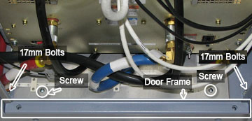
- Remove the lower door frame shown in Figure 13.
- Unplug both leak sensor strip connectors on the far left side of the tray. See Figure 2
- Remove the two 17 mm bolts shown in Figure 13.
- Remove the tray from the cabinet.
- Remove all 14 retainers holding the leak sensor strip to the
cabinet.
Figure 14. Remove 14 Leak Sensor Strips
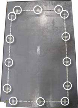 note:
note:The sensor is folded at the corners. This configuration will be repeated during installation of the new sensor strip.
- Remove the sensor strip.
Installing Leak Sensor Strip
Procedure
- Start routing the new leak sensor strip clockwise approximately
1 inch from the left edge of the tray. Seat the strip so that the
second and third open wire holes fall on either side of the retainer. note:
When routing this leak sensor strip, it does not matter which end is used. The ends are interchangeable.
Figure 15. Routing the Leak Sensor Strip
Be sure the retainer lays properly on top of the sensor strip before tightening. See Figure 5.
- Tighten the nuts for each retainer.
- Continue routing the leak sensor strip and retainers, making
sure that bends do not cause the open wire holes to cross each other.
See Figure 6.
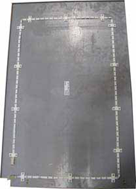
Figure 16. Fully Routed Leak Sensor Strip
- Position the RF leak sensor tray at the base of the cabinet.
- Tighten the two screws to secure the tray to the cabinet.
- Reinstall the 17 mm bolts Figure 13.
- Reinstall the lower door frame Figure 13.
- Reconnect the leak sensor strip connectors.
Finalization
Finalization
Remove LOTO from the PDU. See the MR Service Safety Manual, PN 5452735.