- id_12374933
- Version: 1.2
- Date: Jul 5, 2019 6:08:29 PM
Auxiliary Board Replacement
Prerequisites
| Required persons | Preliminary requirements | Procedure | Finalization |
|---|---|---|---|
| 1 | Not Applicable | 30 minutes | Not Applicable |
| Item | Quantity | Effectivity | Part number | Manufacturer |
|---|---|---|---|---|
| Non-Magnetic Tool Kit (or equivalent) | 1 | - |
5113258 |
- |
| Item | Quantity | Effectivity | Part number | Manufacturer |
|---|---|---|---|---|
| Tie Wraps | 2 | - | - | - |
| Item | Quantity | Effectivity | Part number | Manufacturer |
|---|---|---|---|---|
| Auxiliary Board | 1 | - |
5161071 |
- |
| Condition | Reference | Effectivity |
|---|---|---|
|
The PDU must be powered off. |
- | - |
Procedure
- Perform LOTO on the PDU. See the MR Service Safety Manual, PN 5452735.
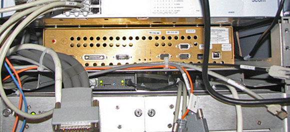
- note:Disconnect the cables on the front of the auxiliary board.
The PDU must be powered down completely to prevent damage to system electronics.
Figure 1. Auxiliary Board - Front Cables Disconnected
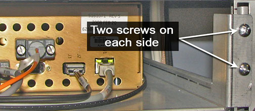
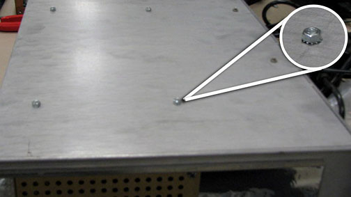
- Undo the four screws on the front shelf holding the auxiliary
board.
Figure 2. Shelf Screws
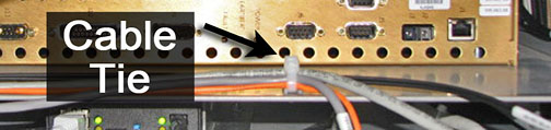
- Before pulling the shelf out, locate the two cable ties in the
front of the auxiliary board shelf. Cut these ties to free the cables.
Then, carefully moves cables away from the shelf so they do not catch
when the shelf is being pulled out.
Figure 3. Cable Ties
- Slowly pull the auxiliary board and shelf out of the cabinet.
Figure 4. Auxiliary Board - Slide Out
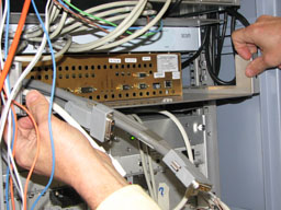
- Before removing the shelf from the cabinet, disconnect any cables from the rear of the auxiliary board.
- Pull the shelf out completely and turn it top side down on a flat surface, exposing the bottom of the shelf.
- The auxiliary board is mounted onto the shelf with six studs.
Detach the auxiliary board from the shelf by unscrewing the nuts.
Keep the nuts; you will need them to attach to the auxiliary board
FRU.
Figure 5. Underside of Shelf
- On the auxiliary board FRU, remove the red safety caps from each of the studs before placing the auxiliary board on the shelf.
- Align the auxiliary board FRU studs with the openings in the shelf. Attach the auxiliary board FRU to the shelf by screwing the nuts onto the six studs.
- Plug in all of the rear auxiliary board cables to the new auxiliary board.
- Align the shelf on the cabinet tracks and push the auxiliary board into the PGR cabinet.
- Secure the shelf into the cabinet with the two screws on each side Figure 2.
- Reconnect the cables to the front of the auxiliary board.
Figure 6. Cable Tie Wrap Holders
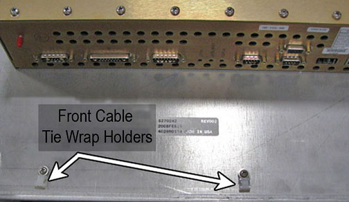
- Place the new tie wraps onto the front of the auxiliary board shelf.
- Place the cables in the tie wraps and secure. Cut any excess tie wrap material.
Finalization
- Remove LOTO from the PDU. See the MR Service Safety Manual, PN 5452735.
- Perform a TPS reset and review the error log for auxiliary board faults.
- Perform a verification scan with the DQA phantom.