- id_13106474
- Version: 4.0
- Date: Feb 14, 2020 4:07:17 PM
KASC assembly replacement
Prerequisites
| Required persons | Preliminary requirements | Procedure | Finalization |
|---|---|---|---|
| 1 | Not Applicable | 30 minutes | For DV: 30 mins. For Voyager and Pioneer: 60 mins. |
| Item | Quantity | Effectivity | Part number | Manufacturer |
|---|---|---|---|---|
| Standard Tool | 1 | - | - | - |
| RF power measurement kit (use one of the following kits): | 1 | - |
EITHER 5307511-2 or 5307511-3 (Bird wattmeter) |
- |
| Item | Quantity | Effectivity | Part number | Manufacturer |
|---|---|---|---|---|
| KASC Assembly | 1 | - |
Refer to FRU Manual |
- |
note:
The unit can be withdrawn with the slide rail. |


Procedure
- notice
- From the Common Service Desktop, turn off the ICN(s) (see ICN On/Off Procedure).
- Complete LOTO for reconstruction equipment. See the latest revision of the MR Service Safety Manual, PN 5452735, available from the online documentation library.
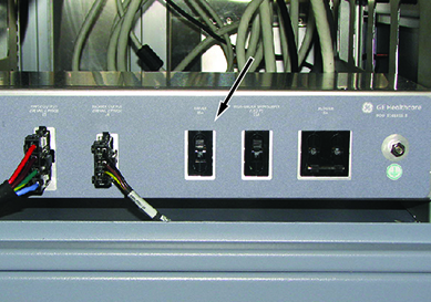
- In the PEN cabinet, turn off the circuit breaker to the driver module.
Figure 1. Driver module circuit breaker (in PEN cabinet)
- Open the PGR cabinet.
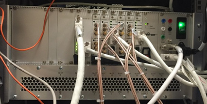
- Disconnect all connectors and cables from KASC.
Figure 2. KASC assembly and cables
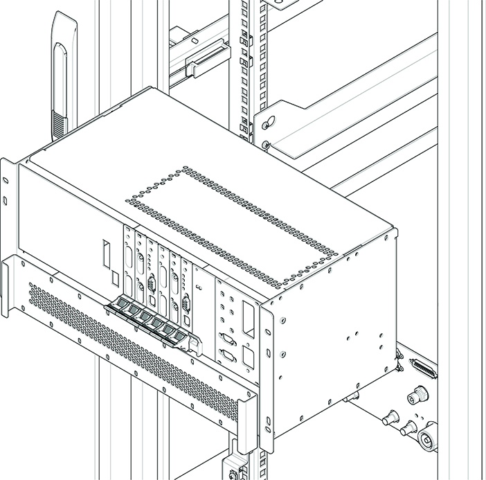
- Remove the KASC assembly as follows:
- Remove four screws.
- Slide the KASC out.
Figure 3. KASC assembly
- Install the new module by reverse order of removal.
 |
Finalization
- Restore the power.
- In the PEN cabinet, turn on the circuit breaker to the driver module.
- Remove LOTO from the reconstruction equipment. See the MR Service Safety Manual, PN 5452735.
- Turn on the ICNs per the ICN On/Off Procedure. note: For the first 3 or 4 minutes, LEDs come on only at the rear of the ICN, next to the power cables. After 3 to 4 minutes, you will hear the ICN fans come on, and then the LED at the front of the ICN starts to flash.
- Do Calibrating RF Amplifier and UPM.
- Do a TPS Reset, and then do a check scan to make sure the system operates correctly.