- id_12373705
- Version: 1.2
- Date: Jul 5, 2019 6:08:29 PM
Terminal Server Replacement
Prerequisites
| Required persons | Preliminary requirements | Procedure | Finalization |
|---|---|---|---|
| 1 | Not Applicable | 30 minutes | Not Applicable |
| Item | Quantity | Effectivity | Part number | Manufacturer |
|---|---|---|---|---|
| Adjustable Wrench | 1 | - | - | - |
| Item | Quantity | Effectivity | Part number | Manufacturer |
|---|---|---|---|---|
| Terminal Server | 1 | - |
|
- |
| Condition | Reference | Effectivity |
|---|---|---|
|
The Auxiliary Board or Power Equipment Monitor (PEM) needs to be removed first in order to access the terminal server. See the Auxiliary Board Replacement or the Power Equipment Monitor (PEM) Replacement procedure. |
- | - |
Procedure
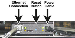
- Disconnect the Ethernet and power cable from the front of the
terminal server.
Figure 1. Front of Terminal Server
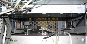
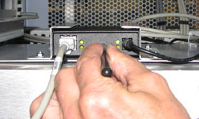
- Push the terminal server back through brackets before disconnecting
the wires in the back.note:
You may have to loosen the bracket mounting nut to easily slide out the terminal server.
Figure 2. Terminal Server - Outside of Holding Bracket
- When the terminal server is outside of the brackets, disconnect the rear wires. Confirm that all the cables are properly labeled to aid re-connection.
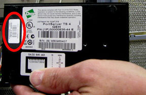
- Before putting the new terminal server into the cabinet, record
the MAC address on the bottom of the terminal server. This address
will be used in Step 8.d.
Figure 3. MAC Address on Terminal Server
- Install the replacement terminal server. After the rear wires are plugged into the new server, push the terminal server through the rear of the brackets towards the front.
- Install the PEM or AUX.
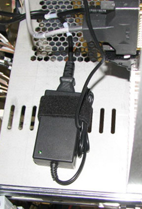
- Connect the front Ethernet and power cables Figure 1. Once the power
cable is connected, a steady green LED should be on the power supply.
The power supply for the terminal server is located on the CAM Chassis
shelf. You may have to pull out the CAM Chassis in order to properly
view the power supply LED.
Figure 4. Terminal Server Power Supply
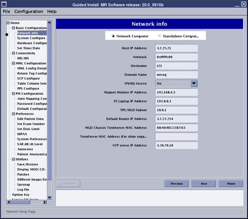
- Change the terminal server MAC address in the Guided Install.
- Click on the Tools icon and select the Service Desktop Manager tab.
- Click Guided Install and then click Start.... Enter in the root login
when prompted.note:
It is possible that the customer changed the default password. If you cannot log in, contact the customer for the correct password.
- Select Network Info from the left-hand navigation sidebar.
- Enter in the new MAC address.
- Click Configure.
Figure 5. Guided Install - MAC Address Entry
- Click File and select .
- Perform a reset on the replacement terminal server.
- Press and hold in the small blue button on the front of the
server.
Figure 6. Terminal Server - Reset Button
- Continue to hold the reset button, then remove the DC power cable while still holding in the reset button. Reinstall the power cable. The LED blinks on and off in a 1:5:1 sequence. If you interrupt the continuous hold momentarily, by slip or mistake, the 1:5:1 sequence will not appear. If this is the case, repeat until the LED blink sequence is as noted. Once the LED is on continuously, it has received its IP from the host.
- Press and hold in the small blue button on the front of the
server.
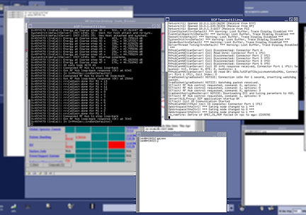
- Open the mgd_term windows to verify connections to AGP and SCP.
- Click C Shell in the Service Desktop Manager.
- Type mgd_term and press Enter.
Figure 7. AGP and SCP Windows from mgd_term Command
- Perform a TPS Reset. Review the error log for any faults.
Finalization
- Perform Verification of SaveInfo Data to save the updated Guided Install information.
- Perform a scan to verify proper system performance.