- id_12373549
- Version: 1.7
- Date: Oct 11, 2019 10:34:09 AM
RF Body or Head Transmit Cable Replacement
Prerequisites
| Required persons | Preliminary requirements | Procedure | Finalization |
|---|---|---|---|
| 1 | Not Applicable | 2 hours | 60 minutes |
| Item | Quantity | Effectivity | Part number | Manufacturer |
|---|---|---|---|---|
| Adjustable Wrench | 1 | - | - | - |
| Phillips-Head Screwdriver (+) | 1 | - | - | - |
| Service Platform | 1 | - |
5155291-2 |
- |
| Item | Quantity | Effectivity | Part number | Manufacturer |
|---|---|---|---|---|
| Tie-Wraps | 3 to 5 | - | - | - |
| Towels (for absorbing coolant) | As needed | - | - | - |
| Item | Quantity | Effectivity | Part number | Manufacturer |
|---|---|---|---|---|
| RF Body Transmit Cable | 1 | - |
See FRU Manual |
- |
| RF Head Transmit Cable | 1 | - |
See FRU Manual. |
- |
|


| Condition | Reference | Effectivity |
|---|---|---|
|
The power in the cabinet needs to be removed. See the MR Service Safety Manual, PN 5452735.. |
- | - |
Overview
This document provides instruction to replace a faulty RF transmit cable. Replacement of the RF transmit cables is constrained by the configuration of the equipment room. There are two procedures for replacing RF transmit cables:
-
If the clearance on the right side of the PGR cabinet is at least 24 inches (61 cm), use the procedure in Replacing RF Body or Head Transmit Cable (Removing Side Cover). This is the easiest procedure and involves removing the right side cover of the PGR cabinet to access the cables.
-
If clearance on the right side of the PGR cabinet is less than 24 inches (61 cm), use the procedure in Replacement of RF Body or Head Transmit Cable (Without Removing Side Cover). In this procedure, the RF amplifier is pulled out of the cabinet (except for systems with the 1.5T XRFD amplifier, which does not need to be pulled out) to allow the RF transmit cables to be routed in the cabinet,
Both of these procedures apply to the 1.5T SRFD2, 1.5T XRFD, 3.0T XRFD, and dual drive RF amplifiers. The details of these procedures vary for each amplifier. Instructions that only apply to a given amplifier are noted.
Replacing RF Body or Head Transmit Cable (Removing Side Cover)
Use this procedure if you have at least 24 inches (61 cm) of clearance on the right side of the PGR cabinet. Otherwise, see Replacement of RF Body or Head Transmit Cable (Without Removing Side Cover).
Removing RF Body or Head Transmit Cable
Procedure
- Perform LOTO on the PGR cabinet. See the MR Service Safety Manual, PN 5452735.
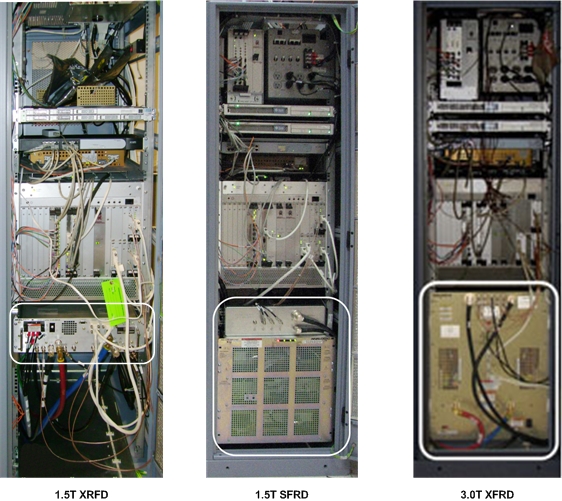
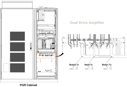
- Using an adjustable wrench, disconnect the failed RF body or
head transmit cable from the front of the RF amplifier.
To access the RF transmit cables, you may need to disconnect other cables.
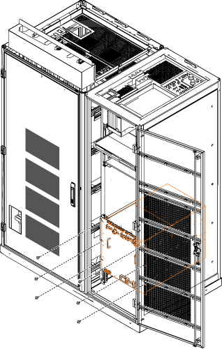
Figure 1. RF Amplifier Location in PGR Cabinet
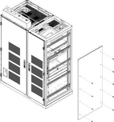
- Remove the right side cover to access the RF transmit cables.
Figure 2. Removing PGR Right Side Cover
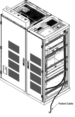
- Pull the end of the defective cable out of the side of the PGR
cabinet. Label the cable as defective.
Figure 3. Pulling Defective Cable from Side of PGR
- notice
- Set up the service platform in front of the PGR cabinet.
- Using an adjustable wrench, remove the body and head transmission
lines from the plate at the top of the PGR cabinet and move them out
of the way.
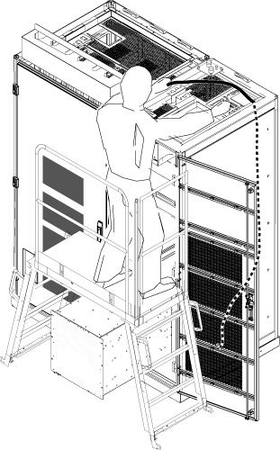
Figure 4. Plate Location on PGR Cabinet and RF Body and Head Transmission Lines
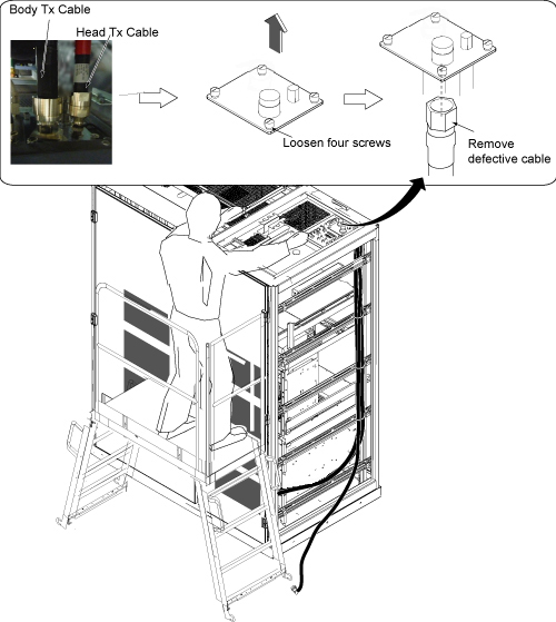
- Remove the plate shown in Figure 4 by loosening 4 thumb screws.
- Disconnect the defective cable from the bulkhead I/F connector.
- Cut the tie wraps securing the transmit cables and remove the defective cable.
 |
Installing New RF Body Transmit Cable
Procedure
- Connect the RF transmit cables to the bottom of the cabinet I/F plate, install the cabinet I/F on the top of the cabinet, and reconnect the transmit cables to the top of the cabinet.
- Remove the service platform.
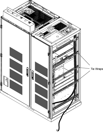
- Tie wrap the RF transmit cables.
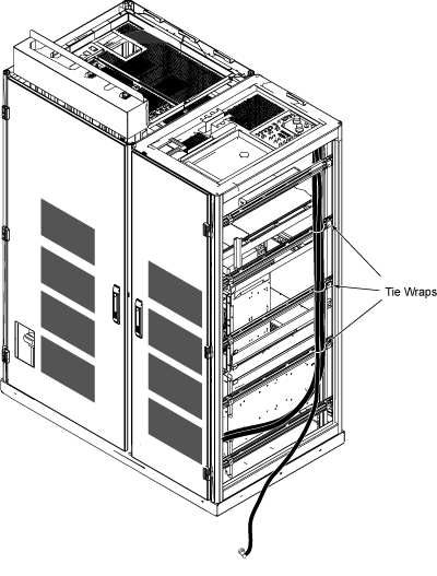
Figure 5. Tie Wrap Locations
- Route the connector for the replacement cable from the right side of the cabinet to the front panel of the RF amplifier.
- Reinstall the right side cover of the PGR cabinet.
- Connect the replacement transmit cable to the RF amplifier. If you disconnected other cables to gain access to the transmit cable, reconnect those cables as well.
- Remove LOTO from the PGR cabinet. See the MR Service Safety Manual, PN 5452735.
- Go to Finalization.
Replacement of RF Body or Head Transmit Cable (Without Removing Side Cover)
Use this procedure if there is less than 24 inches (61 cm) of clearance on the right side of the PGR cabinet. If there is sufficient clearance, use Replacing RF Body or Head Transmit Cable (Removing Side Cover).
Removing RF Body or Head Transmit Cable
Procedure
- Perform LOTO on the PGR cabinet. See the MR Service Safety Manual, PN 5452735.
-
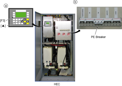
(For 3.0T XRFD and dual drive amplifiers) Shut
down the Power Electronics (PE) pump at the Heat Exchange Cabinet
(HEC) as follows:
- Press ▲ and F3 simultaneously.
- Switch the PE circuit breaker to OFF.
Figure 6. Shutting Down PE Pump
- Disconnect the failed transmit cable from the front of the RF
amplifier and label the cable as defective.note:
There is no need to remove the other cables or cooling lines from the 1.5T XRFD amplifier. This amplifier remains in place during the procedure. (The other amplifiers are slid out of the PGR cabinet to perform this procedure.)
- (For 1.5T SRFD2 and 3.0T XRFD amplifiers) Move the disconnected cables to the side of the cabinet so that the amplifier will be free to move when it is pulled out of the cabinet.
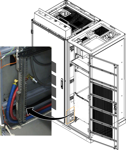
- (For 3.0T XRFD and dual drive RF amplifiers) Disconnect the coolant lines from the front of the RF amplifier. Use a towel to wipe up any dripping coolant.
-
(For 3.0T XRFD and dual drive RF amplifiers) Carefully move the disconnected coolant lines to the left side of
the cabinet, allowing the surrounding area to be free from any obstruction
when the amplifier is pulled out. The following illustration shows
where to place these lines.
Figure 7. Moving Coolant Lines (3.0T XRFD and Dual Drive RF Amplifiers)
-
(For 1.5T SRFD2 and 3.0T XRFD amplifiers) Unscrew
the six screws attaching the RF amplifier to the cabinet rails and
slide the amplifier out of the cabinet.
Figure 8. Six Attachment Screws
- notice
- Set up the service platform in front of the PGR cabinet. If the amplifier is extended out of the cabinet, place the platform over the amplifier.
- Using an adjustable wrench, remove the RF body and head transmission cables from the plate at the top of the PGR cabinet (Figure 9) and move them out of the way.
- Remove the plate shown in Figure 9 by loosening
4 thumb screws.
Figure 9. Plate Location on PGR Cabinet and Body and Head Transmission Lines
- Disconnect the defective transmit cable from the bulkhead I/F connector.
- Label the failed cable as defective, then coil the cable and secure it with tie wrap at the rear of the cabinet.
|
Installation of New RF Transmit Cable
Procedure
- From the top of the PGR cabinet, route the end of the replacement
RF transmit cable with the 90 degree connector into the cabinet so
that it passes through the rear opening of the cabinet to the bottom
of the cabinet.
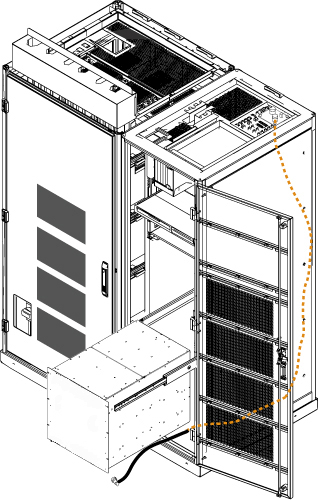
Figure 10. RF Transmit Cable Routing
- Connect the RF transmit cables to the bottom of the cabinet
I/F plate, install the cabinet I/F plate on the top of the cabinet,
and reconnect the RF transmit cables to the top of the cabinet.
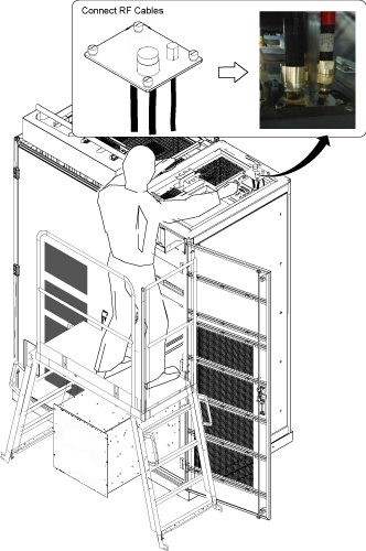
Figure 11. Reconnect Cables on Plate
- Attach the replacement cable toward the rear of the PGR cabinet,
using tie wraps to hold it in place.
Figure 12. Tie Wrapping Transmit Cable
- Remove the service platform.
- Route the end of the replacement cable under the RF amplifier
to the front of the amplifier.
Figure 13. Routing RF Transmit Cable under RF Amplifier
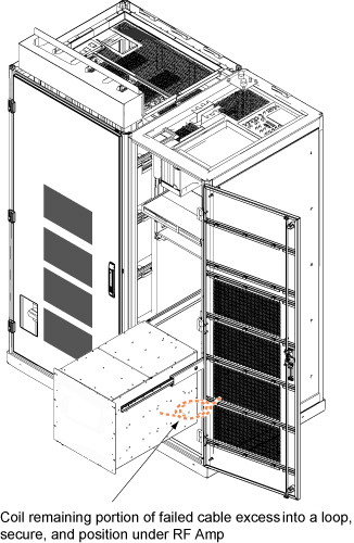
- Coil the excess of the failed cable (with defective label) into
a loop, secure it with a tie wrap, and place it under the RF amplifier.
Figure 14. Coiling Failed Cable
- (For 1.5T SRFD2, 3.0T XRFD, and dual drive RF amplifiers) Slide the RF amplifier back into the PGR cabinet and secure it to the cabinet mounting rails.
- Reconnect the cables to the front of the RF amplifier.
- (For 3.0T XRFD and dual drive RF amplifiers) Reconnect the coolant hoses to the RF amplifier.
-
(For 3.0T XRFD and dual drive RF amplifiers) Restart the Power Electronics (PE) pump at the Heat Exchange Cabinet
(HEC) as follows:
- Switch the PE circuit breaker to ON.
- Press ▲ and F3 simultaneously.
Figure 15. Restarting PE Pump

- Remove LOTO. Restore power to the PGR chassis. See the MR Service Safety Manual, PN 5452735.
- Proceed to Finalization.
Finalization
Procedure
- Perform Check Scan.