- id_12374941
- Version: 1.1
- Date: Jul 5, 2019 10:03:33 PM
Power Equipment Monitor (PEM) Replacement
Prerequisites
| Required persons | Preliminary requirements | Procedure | Finalization |
|---|---|---|---|
| 1 | Not Applicable | 30 minutes | Not Applicable |
| Item | Quantity | Effectivity | Part number | Manufacturer |
|---|---|---|---|---|
| Non-Magnetic Tool Kit (or equivalent) | 1 | - |
5113258 |
- |
| Item | Quantity | Effectivity | Part number | Manufacturer |
|---|---|---|---|---|
| Tie Wraps | 2 | - | - | - |
| Item | Quantity | Effectivity | Part number | Manufacturer |
|---|---|---|---|---|
| Power Equipment Monitor (PEM) Chassis | 1 | - |
See FRU manual |
- |
| Condition | Reference | Effectivity |
|---|---|---|
|
PDU must be powered off. |
- | - |
Procedure
- Perform LOTO on the PGR PDU/gradient subsystem. See the MR Service Safety Manual, PN 5452735.note:
The PDU must be powered down completely to prevent damage to system electronics.
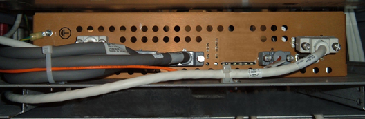
- Disconnect the cables on the front of the PEM chassis.
Figure 1. PEM Chassis
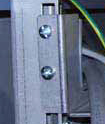
- Remove the four screws holding the PEM chassis (two on each
side).
Figure 2. Mounting Screws
- Before pulling out the PEM chassis, check to see if any cables will prevent easy removal of the PEM chassis. Cut the two wire ties and gently move any cables away from the shelf so they do not catch when the PEM chassis is pulled out.
- Remove the PEM chassis.note:
There are no cables on the back of the PEM chassis.
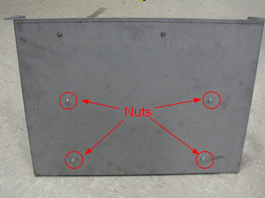
- After removing the PEM chassis from the PGR cabinet, remove
the module from the shelf by removing the 4 nuts.
Figure 3. Nuts on Shelf for PEM Chassis
- Install the replacement PEM chassis onto the shelf.
- Slide the PEM chassis into the PGR cabinet under the ICN tray. The cabinet supports for the PEM chassis have two raised flanges that serve as stops for the rear of the PEM chassis platform.
- Secure the PEM chassis to the cabinet with the four screws (two on each side). See Figure 2.
- At the front left corner of the PEM chassis, attach the ground cable to the ground stud.
- Reconnect the cables to the PEM chassis.
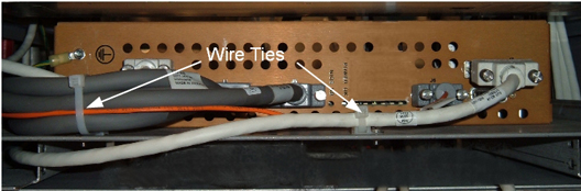
- Secure the leak sensor cable and the PEM board IF cable with
a cable tie through the right anchor on the front of the PEM chassis
platform. Then secure the leak sensor cable, PEM board IF cable, PEM
board fan tray cable, and 48V PDU-PEM board cable with a second wire
tie through the left anchor.
Figure 4. PEM Chassis Wire Tie Anchors
Finalization
- Remove LOTO from the PDU. See the MR Service Safety Manual, PN 5452735.
- Perform a TPS reset and review the error log for any PEM chassis faults.
- Perform a verification scan with the DQA phantom.