- id_13106463
- Version: 4.0
- Date: Feb 14, 2020 4:01:04 PM
ICN Replacement (Dell R620, Dell R630, Sun 4100, 4170, or 4170 M2)
Prerequisites
| Required persons | Preliminary requirements | Procedure | Finalization |
|---|---|---|---|
| 2 | 10 minutes | 30 minutes per ICN | 30 minutes |
| Item | Quantity | Effectivity | Part number | Manufacturer |
|---|---|---|---|---|
| Dell R620 – Image Compute Node (ICN) (Requires minimum software release of 25) | 1 | - |
Refer to FRU Manual |
- |
| Dell R630 – Image Compute Node (ICN) (Requires minimum software release of 25.1 M4) | 1 | - |
Refer to FRU Manual |
- |
| Sun 4100 – Image Compute Node (ICN) | 1 or as required | - |
Refer to FRU Manual |
- |
| Sun 4170 – Image Compute Node (ICN) | 1 | - |
Refer to FRU Manual |
- |
| Sun 4170 M2 – Image Compute Node (ICN) (Requires minimum software release of 22.1) | 1 | - |
Refer to FRU Manual |
- |
| 4170 ICN Hardware FRU Kit | 1 | - |
Refer to FRU Manual |
- |
|


This procedure provides instructions to replace four types of Image Compute Nodes (ICNs): Dell R620/R630, Sun 4100, Sun 4170, and Sun 4170 M2. Also, upgrade instructions are provided for Sun 4100 to Sun 4170 and Sun 4100 to Sun 4170 M2.
-
For replacement instructions for Dell R620/R630, see Replacing Dell R620/R630 ICN.
-
For replacement instructions for Sun 4100, 4170, and 4170 M2, see Replacing Sun 4100 or Sun 4170 ICN.
-
For upgrade instructions from Sun 4100 to Sun 4170 or Sun 4100 to Sun 4170 M2, see Replacing ICN 4100 with 4170/4170 M2.
Refer to the following table to determine the appropriate Gen Type and compare this with the ICN part number at the site. Consult the FRU manual to order the correct replacement power supply or supplies.
| ICN Type | Part Number Series |
| R620 (Gen 5) | 5921000x |
| R630 (Gen 6) | 5931000x |
Replacing Dell R620/R630 ICN
Procedure
- notice
- From the Common Service Desktop, turn off the ICN(s) ICN On/Off Procedure
- Perform LOTO on the reconstruction equipment. See the MR Service Safety Manual, PN 5452735.
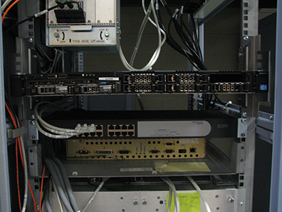
- Locate the ICN in the PGR cabinet, located above the CAM chassis
on the right side.
Figure 1. Locate Dell R620 in PGR Cabinet
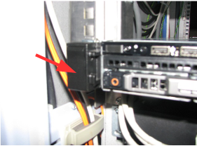
- On the front of the ICN, lift up on the locking tabs on the
right side and the left side of the ICN.
Figure 2. Locking Tab on Left Side of Dell R620
- Slide the ICN out of the cabinet until the stops are reached at the end of the slide rails.
- Remove all connections from the rear of the ICN. Note the locations
for reinstallation.
- Confirm the Ethernet release tabs are completely pressed and released before the cables are removed.
- Remove the AC power plug(s). Depending on configuration, this unit can have one or two power plugs.
Figure 3. Dell R620/R630 Rear View (with VRF)
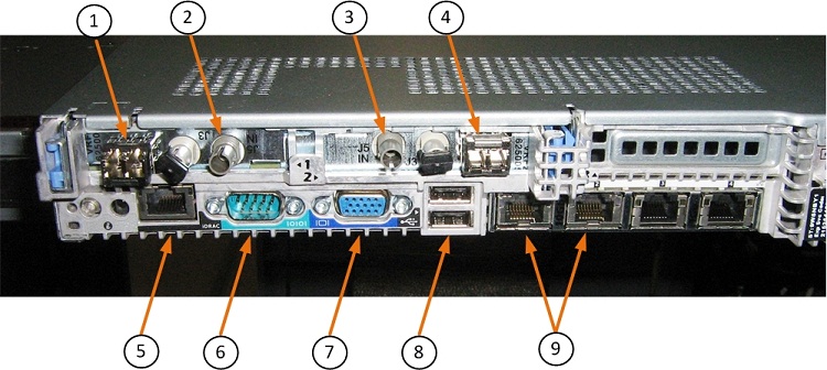
Figure 4. Dell R630 Rear View (without VRF)
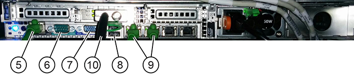
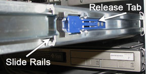
Item Description 1 VRF1 J1 dual VRF fiber 2 VRF1 J5 single clock fiber 3 VRF2 J5 single clock fiber 4 VRF2 J1 dual VRF fiber 5 Net management Ethernet connection 6 Serial port (not used) 7 Video port (not used) 8 USB ports (not used) 9 Net 1 and 2 Ethernet connections 10 PCIe (R630 only) - Locate the two release tabs on the slide rails. Press each release
tab down so that the ICN can be slightly moved forward.
Figure 5. Slide Rails and Release Tabs
- After sliding the ICN forward, lift the ICN up to release from
the bracket.
There are four studs on each side of the ICN that fit into the rail.
Figure 6. Removing ICN from Rails
- Place the old ICN out of the way in a safe area.
- With the slide rails out, install the new ICN, lining up the studs on the ICN with the slots on the rails.
- Slide the ICN back into the PGR cabinet.
- Reconnect all the cables Figure 3.
- Press the release tabs. Push the ICN into the PGR cabinet until the ICN is completely inside and the ICN is locked in place.
- Proceed to Finalization.
 |
Replacing Sun 4100 or Sun 4170 ICN
Procedure
- notice
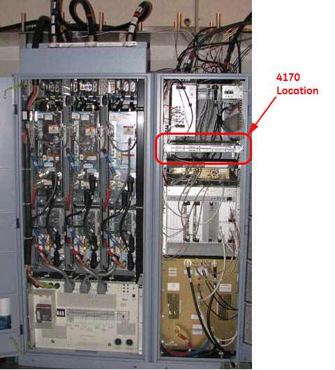
- Locate the ICNs in the PGR cabinet, about 1/3 way from the top
of the cabinet, above the CAM chassis, on the right side.
Figure 7. ICN Location - 4100
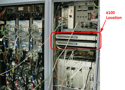
Figure 8. ICN Location - 4170
- From the Common Service Desktop, switch the ICNs off ICN On/Off Procedure.
- Perform LOTO on the reconstruction equipment. See the MR Service Safety Manual, PN 5452735.
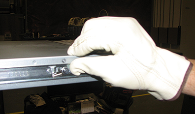
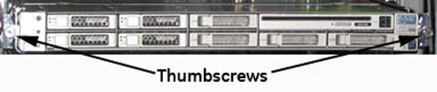
- On the front of the ICN, undo the thumbscrew on each side of
the ICN to be removed/replaced.
Figure 9. Thumbscrews on ICN Front - 4100
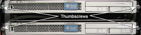
Figure 10. Thumbscrews on ICN Front - 4170
- After the thumbscrews are loose, slide the ICN until the stop is reached at the end of the slide rails.
- Remove all connections from the rear of the ICN. Note the locations
for reinstallation. Be sure that the Ethernet release tabs are completely
pressed before the cables are removed. Remove both AC power plugs.
Figure 11. Infiniband and Ethernet Switch Connections - 4100

Figure 12. Fiber Optic and Ethernet Switch Connections - 4170
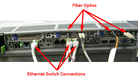
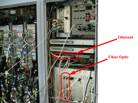
Table 5 ICN Wiring Matrix Connection Item ICN 4170 ICN 4100 32-Channel 16-Channel 32-Channel 16-Channel Power cords 2 2 4 2 Ethernet 3 3 6 3 Duplex fiber optic 2 1 2 1 Single fiber optic 2 1 2 1 Infiniband jumper N/A N/A 1 N/A Fiber optic jumper N/A N/A 1 N/A Figure 13. Ethernet and Fiber Optic Connections
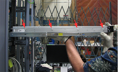
- Locate the two release tabs on the slide rails. Press each release
tab toward the center of the ICN, and pull the ICN forward until the
rails release and the ICN is free. Place the ICN being replaced to
the side in a safe area.
Figure 14. ICN Slide Rails and Release Tabs

- Push the slide rails back into the cabinet before inserting
the ICN.
If upgrading from a 4100 to a 4170 model, proceed to Replacing ICN 4100 with 4170/4170 M2.
Otherwise, transfer each inner slide to the sides of the new ICN module.
- Insert the new ICN into the PGR cabinet. Slide the ICN out until the stop is reached at the end of the slide rails. Make sure release tabs are engaged.
- Connect all the cables back in a reverse operation.
- Press the release tabs. Push the ICN into the PGR cabinet until the ICN is completely inside.
- Attach the thumbscrews to the front of the ICN to secure the ICN into the cabinet.
|
Replacing ICN 4100 with 4170/4170 M2
If a Sun 4100 is being replaced with a 4170 or 4170 M2 ICN, the module(s), the attaching brackets, and slides are removed. New brackets, slides, and ICN are installed.
Removing Sun 4100 ICN(s)
Procedure
- notice
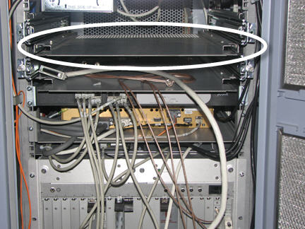
- Locate the ICN 4100 in the PGR cabinet.
Figure 15. Sun 4100 ICN Location

- From the Common Service Desktop, switch the ICNs off (see ICN On/Off Procedure).
- Perform LOTO on the reconstruction equipment. See the MR Service Safety Manual, PN 5452735.
- Loosen the thumbscrews on each side of the ICN.
Figure 16. Thumbscrews Holding Sun 4100 ICN

- Slide out the ICN until the stop is reached at the end of the side rails.
- Remove all the connections at the back of the ICN.
Figure 17. Cable Connections on Sun 4100 ICN

- Locate the two release tabs on the slide rails. Press both release
tabs toward the center of the ICN while pulling the ICN forward. Pull
the ICN forward until the rails release and the ICN is free. Place
the ICN to the side in a safe area.
Figure 18. Slide Rails and Release Tab
- Remove the ICN trays from the ICN mounting brackets.
Figure 19. Sun 4100 ICN Trays
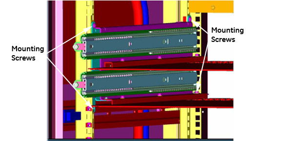
- Remove the screws securing each mounting bracket for the ICN.
- Unfasten and save the M6 nuts that attach the slide to the bracket.
Store in a safe place. They will be reused to attach the new slides
to the new brackets.
Figure 20. Side Mounting Brackets for 4100
|
Installing Brackets for 4170 M2 Models
Procedure
- Loosen the mounting screws for the network switch. Slide the
switch down to give access to the mounting location for the slide
rails for the 4170 ICN.
Figure 21. Mounting Rails for 4170 ICN
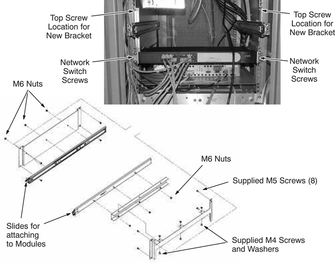
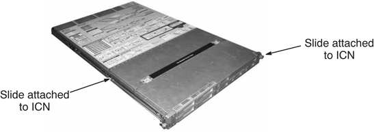
- On each slide (5374804), remove the inner slide so that you
can attach them to the sides of the ICN module.
Figure 22. Fastening Slide to ICN
- Attach the slides to the fixed support bracket (5374805) and inside support bracket (5374806) with the M6 nuts previously removed.
- Attach the inside support bracket to the outside support bracket (5374807) using M4 screws (2109866-3) and washers (46-328431P1). See Figure 21.
- Attach the slide rails for the ICN 4170 module to the mounting rails in the PGR cabinet using four M5 screws on each bracket.
- After brackets are secured, pull the slides forward to install the new ICN module.
- Attach each inner slide to the sides of the new ICN module.
- Push the slide rails back into the cabinet before inserting the ICN.
- Insert the new ICN into the PGR cabinet. Slide the ICN out until the stop is reached at the end of the slide rails. Make sure release tabs are engaged.
- Connect all the cables back in a reverse operation.
- Press the release tabs. Push the ICN into the PGR cabinet until the ICN is completely inside.
- Attach the thumbscrews to the front of the ICN to secure it in the cabinet.
Finalization
Finalization
-
Remove LOTO from the reconstruction equipment. See the MR Service Safety Manual, PN 5452735.
-
Turn the ICNs on per ICN On/Off Procedure.
note: For the first 3 or 4 minutes, LEDs come on only at the rear of the ICN, next to the power cables. After 3 to 4 minutes, you will hear the ICN fans come on and then the LED at the front of the ICN starts flashing. -
Configure the new ICN VRE configuration and reconfiguration.
-
Perform a test scan to ensure the system is working properly.