- id_13106451
- Version: 3.0
- Date: Aug 29, 2019 1:39:32 AM
CAM chassis replacement
Prerequisites
| Required persons | Preliminary requirements | Procedure | Finalization |
|---|---|---|---|
| 1 | Not Applicable | 60 minutes | 30 minutes |
| Item | Quantity | Effectivity | Part number | Manufacturer |
|---|---|---|---|---|
| ESD Grounding Wrist Strap | 1 | - | - | - |
| Phillips Screwdriver | 1 | - | - | - |
| Anti-Static Bags | As needed | - | - | - |
| Item | Quantity | Effectivity | Part number | Manufacturer |
|---|---|---|---|---|
| CAM DC Blower | 1 | - |
See applicable FRU manual. |
- |
| AGP2 Board | 1 | - |
See applicable FRU manual. |
- |
| IRF3 Board | 1 | - |
See applicable FRU manual. |
- |
| IXG Board | 1 | - |
See applicable FRU manual. |
- |
| SCP3 Board | 1 | - |
See applicable FRU manual. |
- |
| SRF/TRF Board | 1 | - |
See applicable FRU manual. |
- |
| STIF Board | 1 | - |
See applicable FRU manual. |
- |
| PSE Board | 1 | - |
See applicable FRU manual. |
- |
| Main Power Supply | 1 | - |
See applicable FRU manual. |
- |
| UPM RF Detector Board | 2 | - |
See applicable FRU manual. |
- |
| UPM Processor Board | 2 | - |
See applicable FRU manual. |
- |
| NB Amp IF Board | 1 | - |
See applicable FRU manual. |
- |
|
Figure 1. CAM chassis layout (front view)
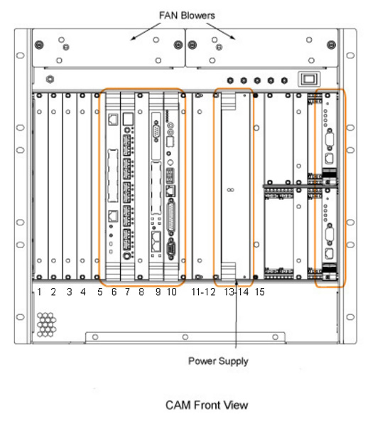
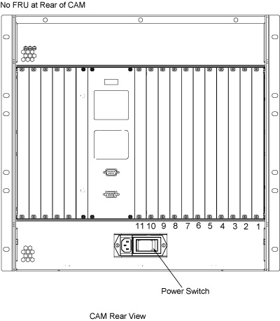
Figure 2. CAM chassis layout (rear)
The Combined ASC/MGD (CAM) chassis includes the Multi-Generational Data (MGD) acquisition components and the Amplifier Support Chassis (ASC) components.
The MGD portion of the chassis contains the circuit boards for the pulse generation, system control, and DVMR fiber-optic link communication subsystems. These boards can be easily accessed from the front and rear of the chassis.
The ASC portion of the chassis contains the circuit boards for the amplifier and Universal Power Monitor (UPM) subsystems. These boards can be easily accessed from the front of the chassis.
The power supply modules located in the front of the chassis supply both the MGD and ASC components.
The following removal and insertion procedures are applicable for all the types of circuit boards located within the card rack. The following topics are found in this document:
- MGD Circuit Board Removal/Replacement MGD circuit board removal/replacement
- ASC Board/UPM Chassis Circuit Board Removal/Replacement ASC board/UPM chassis circuit board removal/replacement
- Power Supply Module Removal/Replacement Power supply module removal/replacement
- Fan Blower Removal/Replacement Fan blower removal/replacement
- CAM Chassis Removal/Replacement CAM chassis removal/replacement
MGD circuit board removal/replacement
Power down CAM chassis
Procedure
- At the host computer, open the Service Browser and select Utilities > Tool Box > VRE > Power Control.
- Select Power Off VRE.
- Perform LOTO for reconstruction equipment, as described in the MR Service Safety Manual, PN 5452735.
Board positions and identification
Procedure
- MGD chassis front board slot assignments are identified below.
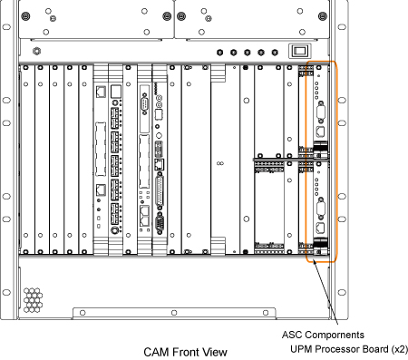
Figure 3. MGD components in CAM chassis - front view
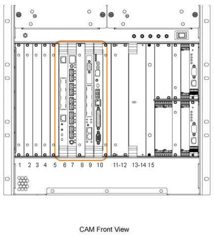
Slot Number(s) Board Name Configuration 1 Configuration 2 1-5 Empty slot Empty slot 6 AGP2 processor board AGP2 processor board 7 IRF3 board IXG board 8 Empty slot ERF (MNS only) 9 SCP3 board SCP3 board 10 - 11 SRF/TRF PSE board 11 - 13 Power supply module or empty slot Empty slot 14 - 15 Power supply module Power supply module - MGD chassis rear board slot assignments are identified below.
Figure 4. MGD components in CAM chassis - rear view
Slot Number(s) Board Name Configuration 1 Configuration 2 1 - 6 Empty slot Empty slot 7 IRF I/O Empty slot 8 - 9 Empty slot Empty slot 10 - 11 STIF board Empty slot or PSE I/O (optional) 12 Empty slot Empty slot
Circuit board removal procedure
Procedure
- Attach an ESD grounding wrist strap.
- Remove the cables (PCI card, 10/100 BaseT, Com1, etc.) from the face of the board.
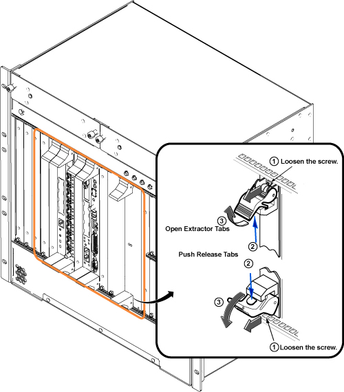
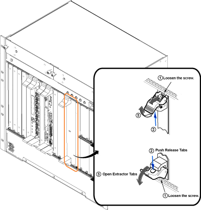
- Loosen the faceplate holding screws. These screws are captive
to the faceplate and do not need to be completely removed.note: If the board is double wide, there are four faceplate holding screws to remove (SRF/TRF board and power supply boards).
- Using your thumb, push in the grey release tabs, and gently
pull the extractor tabs located on the top and bottom of the circuit
board. The lever action of the ejector disengages the circuit board
connections from the chassis.note: The AGP and SCP boards do not have release tabs.
Figure 5. Faceplate release tabs
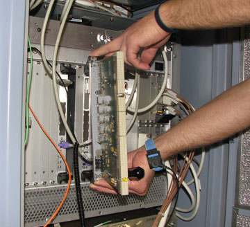
- Being careful not to bend or bind the card in any way, slide
the circuit board all the way out of the card cage.note: Handle the circuit boards only by the faceplate, ejector, and board edges.
- Place the card in an appropriate shipping package, or discard if applicable.
Circuit board replacement
Procedure
- Remove the packing material from the replacement board, and gently slide the circuit board along the slot guides into the chassis.
 danger
- Gently engage the circuit board connectors with the backplane.
- If the circuit board is not properly engaging the backplane, remove the board and check the connectors for bent or broken pins.
- After the board ejectors contact the CAM chassis faceplate, gently push the ejectors into the center of the board. This causes the ejectors to insert the board into the chassis. (Do not use anything other than the ejectors to insert or remove the board from the chassis.)
Figure 6. Board connections
- Tighten, but do not overtighten, the faceplate holding screws to secure the circuit board to the card rack.
- Where applicable, reattach the cables to the face of the board.
 |
Restoring system for clinical applications
Procedure
- Restore power to the CAM chassis.
- Refer to Finalization for checkout and proper operation.
ASC board/UPM chassis circuit board removal/replacement
Power down CAM chassis
Procedure
- At the host computer, open the Service Browser and select Utilities > Tool Box > VRE > Power Control.
- Select Power Off VRE.
- Perform LOTO for reconstruction equipment. See the MR Service Safety Manual, PN 5452735.
ASC board positions and identification
Procedure
- ASC front board slot assignments are identified below.
Figure 7. ASC chassis - front view
- Circuit board parts are identified below.
Upper slots (nU) Lower Slots (nL) Slot number Board name Slot number Board Name 17U - 18U Optional MNS amplifier board slots 17L - 18L Narrow band (NB) amplifier interface board slot 19U Optional MNS detector board slot 19L Optional MNS detector board slot 20U Narrow band (NB) detector board slot 20L Narrow band (NB) detector board slot 21U UPM processor board slot 21L UPM processor board slot
Circuit board removal
Procedure
- Attach an ESD grounding wrist strap.
- Where applicable, remove the cables (sub D, SMB, etc.) from the face of the board.
- Loosen the faceplate holding screws. These screws are captive to the faceplate, and do not need to be completely removed.
- Using your thumb, push in the gray release tab, and gently pull the extractor tab located on the bottom of the circuit board. The lever action of the ejector disengages the circuit board connections from the chassis.
- notice
- Being careful not to bend or bind the card in any way, slide
the circuit board all the way out of the card cage.note: Handle the circuit boards only by the faceplate, ejectors, and board edges.
- Place the card in an appropriate shipping package, or discard if applicable.
 |
Circuit board replacement
Procedure
- Remove the packing material from the replacement board, and gently slide the circuit board along the slot guides into the chassis.
- Gently engage the circuit board connectors with the backplane.
- If the circuit board is not properly engaging the backplane, remove the board and check the connectors for bent or broken pins.
- After the board ejectors contact the CAM chassis faceplate, gently push the ejector into the center of the board. This causes the ejector to insert the board into the chassis. (Do not use anything other than the ejector to insert or remove the board from the chassis.)
- Tighten, but do not overtighten, the faceplate holding screws to secure the circuit board to the card rack.
- Where applicable, reattach the cables and terminators to the face of the board.
Restoring system for clinical applications
Procedure
- Restore power to the CAM chassis.
- Refer to Finalization for checkout and proper operation.
Power supply module removal/replacement
Power down CAM chassis
Procedure
- note: Beginning in August 2009, the CAM chassis has a one power supply configuration in slots 14/15. Functionality is maintained, and the empty slot is covered with a front panel airflow blocker. If a new CAM chassis FRU is ordered, one power supply (slots 14/15) and an additional front panel and airflow blocker (slots 12/13) are installed in the new CAM unit.At the host computer, open the Service Browser and select Utilities > Tool Box > VRE > Power Control.
- Select Power Off VRE.
- Perform LOTO for reconstruction equipment. See the MR Service Safety Manual, PN 5452735.
Power supply module removal
Procedure
- Attach an ESD grounding wrist strap.
- Loosen the two faceplate holding screws at the top and bottom of the faceplate. These screws are captive to the faceplate, and do not need to be completely removed.
- Using your thumb, push in and gently pull the extractor tab
located on the circuit board. The lever action of the ejector disengages
the supply module connections from the chassis.
Figure 8. Power supply faceplate holding screws
- Slide the power supply module all the way out of the card cage.note: Handle the modules only by the faceplate, ejectors, and board edges.
- Place the module in an appropriate shipping package.
Power supply module replacement
Procedure
- Remove the packing material from the replacement module, and gently slide the module into the chassis.
- Use the ejectors to insert the module into the chassis.
- Tighten, but do not overtighten, the faceplate holding screws to secure the power supply module to the card rack.
Restoring system for clinical applications
Procedure
- Restore power to the CAM chassis.
- Refer to Finalization for checkout and proper operation.
Fan blower removal/replacement
Procedure
- At the host computer, open the Service Browser and select Utilities > Tool Box > VRE > Power Control.
- Select Power Off VRE.
- Perform LOTO for reconstruction equipment. See the MR Service Safety Manual, PN 5452735.
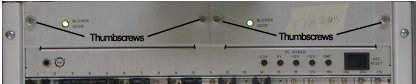
- On the front of the CAM chassis are two fan blower assemblies
(each is held in place with two thumb screws). Loosen the two thumb
screws securing the fan assembly that needs to be replaced.
Figure 9. CAM Chassis Fan Covers
- Pull out the defective fan(s).note: The fan is 'plug and play' with no cables for ease of removal or insertion.
- Slide the new fan into the same slot from which the defective
fan was removed, and push it back into the slot until snug.note: The connector of the fan automatically aligns itself to the plug of the chassis.
- Tighten the two thumb screws to secure the fan assembly.
- Restore power to the CAM chassis.
- Refer to Finalization for checkout and proper operation.
CAM chassis removal/replacement
Power down CAM chassis
Procedure
- At the host computer, open the service browser and select Utilities > Tool Box > VRE > Power Control.
- Select Power Off VRE.
- Perform LOTO for reconstruction equipment. See the MR Service Safety Manual, PN 5452735.
CAM chassis removal
Procedure
- Attach an ESD grounding wrist strap.
- Remove all the circuit boards and store them in a static-safe location. (Refer to Circuit board removal procedure and Circuit board removal for removal instructions.)
- Remove the power supply modules. (Refer to Power supply module removal for removal instructions.)
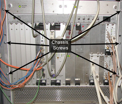
- Remove the six screws that hold the CAM chassis to the cabinet
frame.
Figure 10. CAM chassis screws
- Disconnect all cables.
- Slide the CAM chassis out of the PGR cabinet.
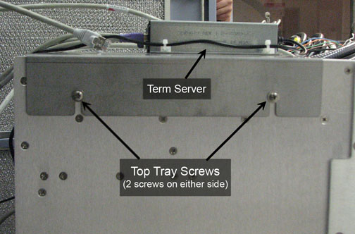
- Remove the top tray on the CAM chassis by loosening the four
screws.
Figure 11. Top tray screws and term server
- Disengage the slide rails, and safely place the CAM chassis on a flat surface.
- Remove the slide rails and the four screws to remove the bottom tray.
- Install the slide rails and bottom tray on the new chassis.note: Ensure that the switch on the back of the CAM chassis is ON.
CAM chassis installation
Procedure
- Attach an ESD grounding wrist strap.
- Slide the CAM chassis into the PGR cabinet.
- Install the top tray with the term server, and reconnect the cables.
- Replace the six screws that hold the CAM chassis to the cabinet frame.
- Install all boards. See Circuit board replacement and Circuit board replacement.
- Replace the power supply modules. See Power supply module replacement.
- Reattach all cables.
Restoring system for clinical applications
Procedure
- Restore power to the CAM chassis.
- Refer to Finalization for checkout and proper operation.
Finalization
Procedure
- If one of the narrow and (NB) or broad band (BB) interface/detector boards or the UPM processor board has been replaced or swapped, run UPM Calibration and UPM Functional Check – Body Mode and UPM Calibration and UPM Functional Check – Head Mode.
- Run a single iteration of Quick Diagnostics (15 minutes) to verify operations.
- Run a goodbye scan. See Doing a check scan.