- id_13106620
- Version: 3.0
- Date: Aug 29, 2019 1:31:54 AM
Ethernet Switch Replacement
Prerequisites
| Required persons | Preliminary requirements | Procedure | Finalization |
|---|---|---|---|
| 1 | Not Applicable | 15 minutes | Not Applicable |
| Item | Quantity | Effectivity | Part number | Manufacturer |
|---|---|---|---|---|
| Standard Service Tool Kit | 1 | - | - | - |
|


| Condition | Reference | Effectivity |
|---|---|---|
|
Turn off all ICNs from the Common Service Desktop. Go to Utilities > Toolbox > VRE > Power Control. Click Power Off for all ICNs. |
- | - |
The Ethernet switch transfers data between the host computer and the PGR cabinet components. The switch is part of the recon subsystem.
Removal of Ethernet Switch
Procedure
- Perform LOTO on the PGR PDU/gradient subsystem. See the MR Service Safety Manual, PN 5452735.
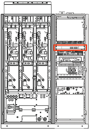
- Locate the Ethernet switch in the right side of the PGR cabinet,
under the ICN.
Figure 1. Ethernet Switch Location (Typical PGR Cabinet Shown)
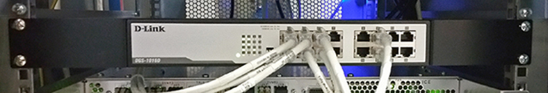
- Remove the Ethernet cables from the front of the switch.
Figure 2. Ethernet Switch - Front View
- Remove the four screws on the front of the switch bracket.
- Pull the switch forward. Disconnect the power plug from the rear of the chassis.
- If the switch is a returnable FRU, repack the defective switch into the FRU packaging and send it back to its destination.
Installation and Power-up
Procedure
- Plug in the power cable to the rear of the switch.
- Slide the network switch into the original position in the PGR cabinet.
- Secure the switch to the cabinet with four screws.
- D-link switches with hardware version G3 or H1 on the rating
plate have DIP switches on the front. Set the DIP switches according
to Table 5.
Figure 3. DIP Switches and LED Indicators
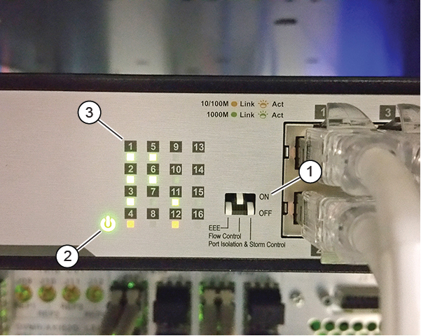
1 DIP switches 2 Power LED 3 Connection LEDs Table 5 DIP Switch Settings DIP Switch Setting EEE OFF Flow Control ON Port Isolation & Storm Control OFF - Reconnect all Ethernet cables to the ports on front of the switch as marked.
- Remove LOTO and power up the unit. See the MR Service Safety Manual, PN 5452735.
- Check that the green power LED is on. Also check the connection LEDs for each connected port (solid green indicates a good connection, and flashing green indicates network activity).
Finalization
Procedure
- Reboot the host computer.
- Perform a verification scan.