The motor-on switch is located in the base of the table dock.
Procedure
Remove the two screws securing the motor-on wire terminal lugs to the motor-on switch.
Note: It is recommended that the wires are marked prior to disconnecting them from the switch.
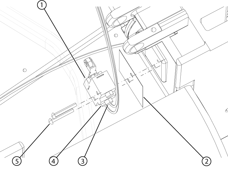
Figure 1. Motor-on switch
1
Motor-on switch
2
Fish paper
3
Motor-on NO wire
4
Motor-on COM wire
5
Switch screw
Remove the two screws securing the switch to table dock.
Remove the switch from the dock.
Note: Retain the fish paper for installation.
Apply Loctite #243 to the two switch screws.
Install the switch into the dock with the fish paper between the switch and the dock wall.
Install the two screws securing the switch to the dock.
Note: Tighten the screws 30 degrees past free spinning.
Install the terminal lugs to the switch.
Install the two screws securing the terminal lugs to the switch.
Topic ID: task_wh2_rnb_wjb
Docked or table ID switch
About this task
The docked and table ID switches are located in the dock top cover. The replacement procedure applies to either switch.
Procedure
Remove the two screws securing the switch wire terminal lugs to the switch.
Note: It is recommended that the wires are marked prior to disconnecting them from the switch.
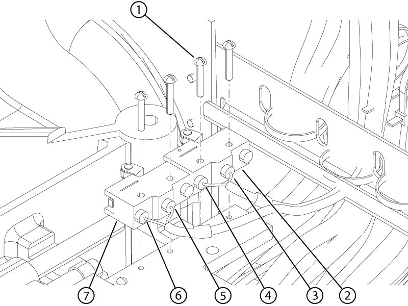
Figure 2. Docked and table ID switches
1
Switch screw
2
Table ID switch
3
Table ID NO wire
4
Table ID COM wire
5
Docked NO wire
6
Docked COM wire
7
Docked switch
Remove the two screws securing the switch to table dock cover.
Remove the switch from the cover.
Apply Loctite #243 to the two switch screws.
Install the switch into the dock cover.
Install the two screws securing the switch to the cover.
Note: Push the switch toward the shaft while tightening the screws.
Note: Tighten the screws 30 degrees past free spinning.
Make sure both switches activate and deactivate by listening for an audible click while cycling the shaft in and out at least three times. Rotate the shaft approximately 120 degrees for each cycle.
Install the terminal lugs to the switch.
Install the two screws securing the terminal lugs to the switch.