Removes the motor and ElectroMagnetic (EM) clutch assembly from the dockable table tabletop.
Prerequisites
| Personnel requirements |
|---|
| Required persons | Preliminary requirements | Procedure | Finalization |
|---|
| 1 | - | 10 minutes | - |
| Tools and test equipment |
|---|
| Item | Quantity | Part number | Manufacturer |
|---|
| Nonmagnetic Titanium Service Tool Kit, Small Set | 1 | 5113258 | - |
| Required conditions |
|---|
| The left- and right-hand table side covers are removed. |
Procedure
- Undock the table and move it out of the scan room.
| Warning |
|---|
| Ferrous material hazard The motor and clutch assembly is ferrous and will be attracted to the magnet. Always remove and install the motor and clutch assembly outside of the scan room. Failure to comply may result in serious injury or death. |
- Disconnect the motor power and signal connectors from the table wiring.
Figure 1. Motor power and signal connectors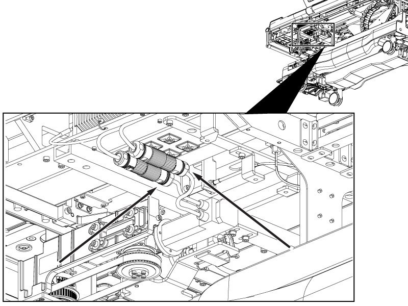
- Remove the cable ties securing the motor connectors to the table.
- Disconnect the EM clutch cable from the table wiring.
Figure 2. EM clutch connector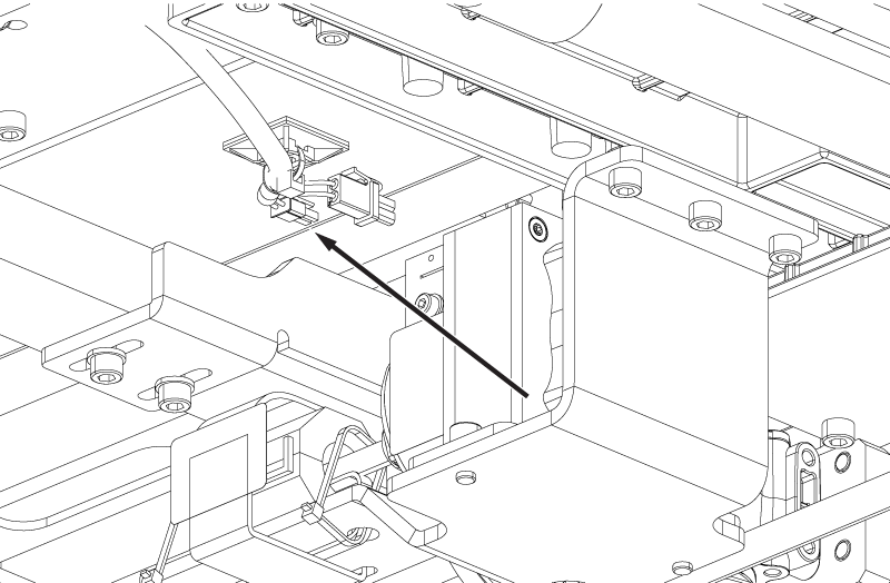
- Raise the table handle.
- Loosen the screw securing the coupler to the rigibelt drive shaft.
Note: If the coupler screw is not accessible, press and hold the dock pedal and move the cradle until the screw is accessible.
Figure 3. Motor coupler screw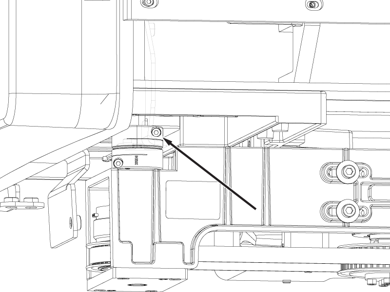
- Remove the four screws securing the motor bracket to the tabletop.
Figure 4. Motor bracket screws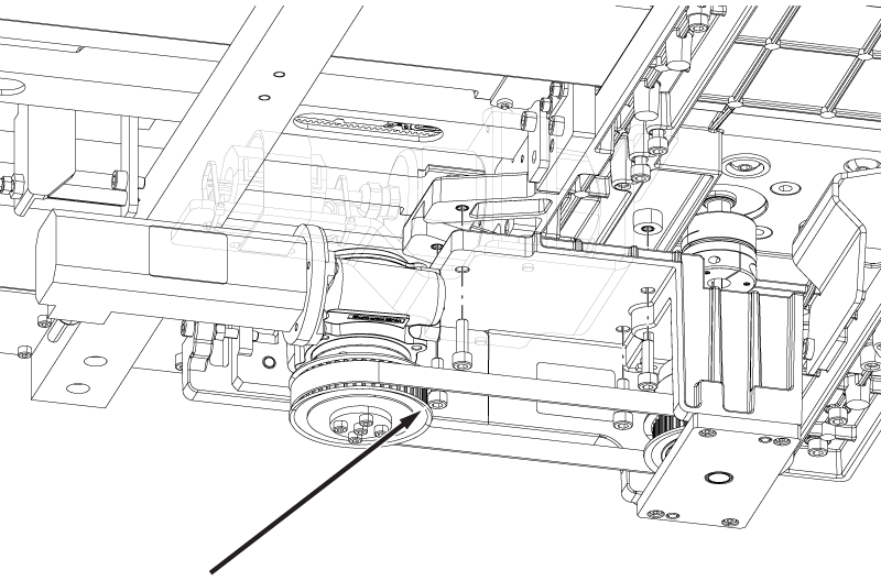
- Remove the motor and EM clutch assembly from the tabletop.
Note: There are two small shaft keys in the coupler. Make sure the keys do not fall out of place during removal.
