
- SIGNA MR355 / SIGNA MR360
- Service Manual
- 5856356-3EN Revision 5.0
- Basic Service Documentation. Copyright General Electric Company.
- 00000018WIA30D42030GYZ
- id_131069751.2
- Jul 6, 2019 12:17:31 AM
XFD Power Panel Assy
Prerequisites
| Required persons | Preliminary requirements | Procedure | Finalization |
|---|---|---|---|
| 1 | Not Applicable | 60 minutes | 15 minutes |
| Item | Quantity | Effectivity | Part number | Manufacturer |
|---|---|---|---|---|
| Non Magnetic Tool Set | 1 | - | - | - |
| Digital volt meter (DVM) | 1 | - | - | - |
| Item | Quantity | Effectivity | Part number | Manufacturer |
|---|---|---|---|---|
| XFD Power Panel Assy (Refer to Illustrated Parts) | 1 | - | - | - |
| ||||||||
| Condition | Reference | Effectivity |
|---|---|---|
|
PDU must be turned OFF. Refer to Lockout / Tagout for MDP(Main Disconnect Panel) or Facility PDU. | - | - |
Procedure
- Turn the SW1 to Discharge on front of XFD-PS.
Figure 1. Discharge 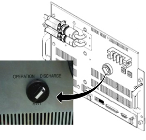
Wait for 30 minutes.CAUTION 
- Remove Cover for XFD Power Pannel Assy.
Figure 2. Cover for XFD Power Pannel Assy. 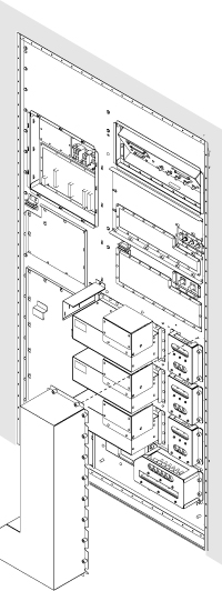
- Check the voltage at each axis terminals (X, Y, Z) and confirm
that there is no voltage. Refer to Figure 3 for voltage
check point.Note:
Normally, the voltage of upper terminal will be 0 V after 30 minutes.
For lower terminal, the voltage may exist in case of switch failure in XFD-PS and the charge of super capacitor cannot be discharged.
If voltage exists in lower terminal, please check that SW1 of XFD-PS is turned to discharge position.
If SW1 is at discharge position, waited for 30 minutes, and voltage still exists at lower terminal, consider to replace XFD-PS before replacing XFD Power Panel Assy.
Figure 3. Voltage Check 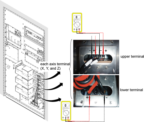
- Remove defective XFD Power Pannel Assy.
Figure 4. Cabinet Interface Board Cables 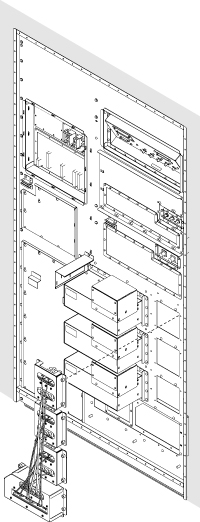
Finalization
Procedure
- Restore the Power. Refer to Lockout / Tagout for MDP(Main Disconnect Panel) or Facility PDU.
- Perform Signal to Noise - Head Scan.