
- SIGNA™ Hero 3.0T Service Methods
- 5852800-8EN Revision 1.0
- 00000018WIA309BC230GYZ
- id_156674061.11
- Jul 13, 2021 4:27:36 PM
SSSA Replacement
Prerequisites
| Required persons | Preliminary requirements | Procedure | Finalization |
|---|---|---|---|
| 1 | Not Applicable | 90 minutes | 30 minutes |
| Item | Quantity | Effectivity | Part number | Manufacturer |
|---|---|---|---|---|
| Standard Tool | 1 | - | - | - |
| Ladder | 1 | - | - | - |
| Hoist Service Kit | 1 | - |
5196226 | - |
| Item | Quantity | Effectivity | Part number | Manufacturer |
|---|---|---|---|---|
| SSSA | 1 | - |
Refer to FRU Manual | - |
| ||||||||||||||||||||||||||||
| Condition | Reference | Effectivity |
|---|---|---|
|
System Power must be turned OFF. Refer to Lockout / Tagout for ISC. | - | - |
Procedure
- Confirm that there is no input voltage at the terminal of SSSPS using DVM.
Figure 1. Voltage Check 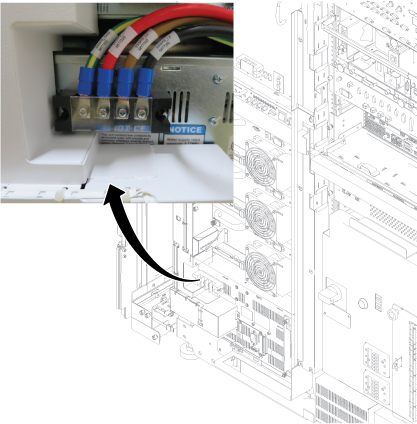
- Remove left front cover per following steps.
- Open left front cover and remove a screw to disconnect GND cable.
- Unlock the cover.
- Lift up and remove the cover.
Figure 2. Cover removal 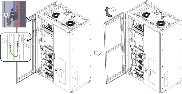 Note: If the service area is narrow, do the same for right front cover.
 - Perform the following steps.
- Disconnect two connectors.
- Remove six screws.
- Remove Leak sensor assy.
Figure 3. Remove Leak Sensor 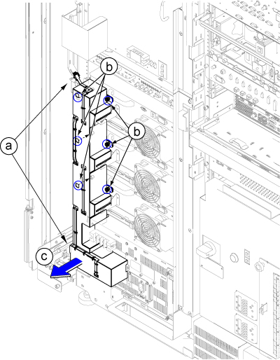
Disconnect the IN and OUT quick couplers of corresponding SSSA from the water manifold.Warning Figure 4. Water Manifold Socket Order 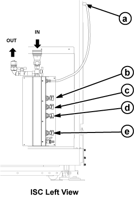
a RF Amp b SSSA (X) c SSSPS d SSSA (Y) e SSSA (Z)
Connect the IN and OUT of quick coupler, and tie the hose as illustration.CAUTION Figure 5. Water Manifold 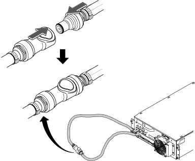
- Disconnect cables and Loosen 4 screws from SSSA.
- Disconnect the all connectors and terminals from front panel of SSSA.
- Loosen 4 screws tightening SSSA front panel to the chassis.
- Withdraw SSSA from the chassis.
Figure 6. SSSA Front 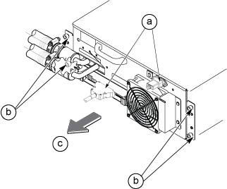
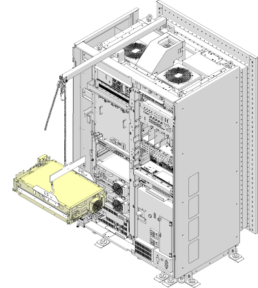
- Install the hoist brackets to the chassis of SSSA with 6 screws. Note: Hoist Bracket is stored in FRU box.
Figure 7. Hoist Brackets Installation 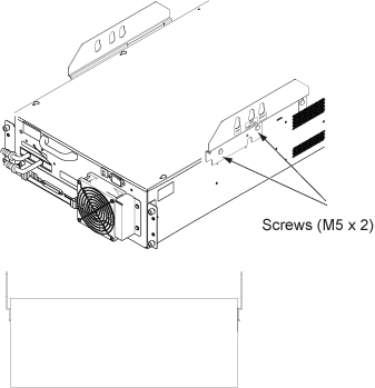
- Perform the following steps.
- Hook the winch and spreader bar from the hoist kit to the lifting bracket named “SSSA WITH FILTER”
- Ratchet the winch to tighten the chain.
- Press the release tabs in on each side and remove the 2nd slide rail from 1st slide rail.
Figure 8. Hoist Operation 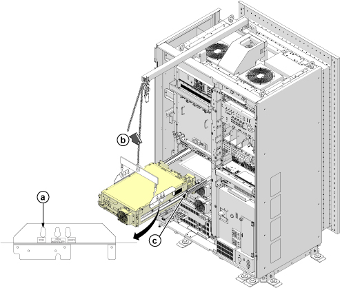
Push the rail slider into the system cabinet before lowering SSSA.Notice 
- Use the hoist and slowly lower the SSSA Chassis to the floor.Note: When lowering the SSSA Chassis, it may be easier to rotate SSSA 90 degree as following illustration.
Finalization
-
Set the RF Amp Breaker to OFF Position.Notice Figure 9. RF Amp Breaker OFF 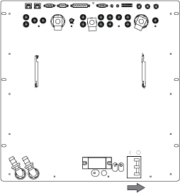
- Restore the System power. Refer to Removing LOTO - ISC.
- Wait till pressure meter (black meter) of CCU moves for about 40 seconds.
Figure 10. Pressure meter 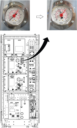
- Turn the RF Amp Breaker ON
Figure 11. RF Amp Breaker ON 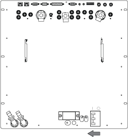
- Refill Coolant. Refer to Refill Coolant .
- To adjust DC Offsets, refer to DC Offset Adjustment.
- Perform [TPS Reset].
- Perform DQA Tool.