Use proper lock out / tag out procedures before servicing and/or maintaining.
Warning
Possible personal injury or equipment damage!
The module could fall when using the lift tool.
Before putting weight on the hoist chain, be sure that the links are aligned properly. This will help keep the chain from binding up, or becoming kinked, which is nearly impossible to correct when the chain is under tension.
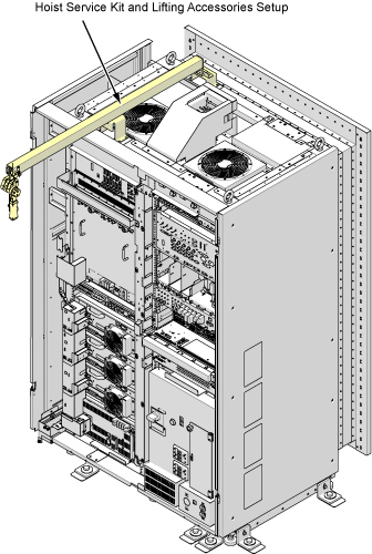
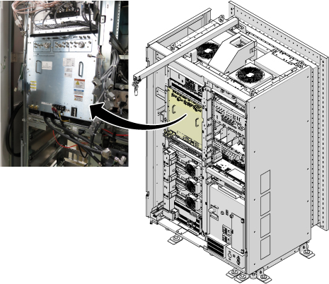
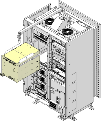
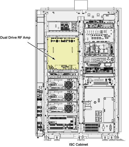
This document contains Dual Drive RF Amp replacement procedure. This unit is in the ISC cabinet (shown below). The Dual Drive RF Amp unit is about 335 lbs (152kg). The unit weighs enough that the use of a hoist kit is required. This document details the correct way to use a hoist kit to remove the Dual Drive RF Amp unit and replace with the field replaceable unit (FRU) safely.
Figure 1. Dual Drive RF Amp
Procedure
CAUTION
Power must be off at least 5 minutes prior to removal of RF Amp.
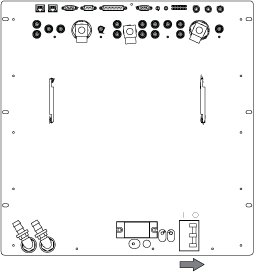
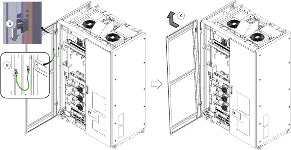
Remove left front cover per following steps.
Open left front cover and remove a screw to disconnect GND cable.
Unlock the cover.
Lift up and remove the cover.
Figure 2. Cover removal
Note: If the service area is narrow, do the same for right front cover.
Perform the Hoist Setup procedure to set up and secure the hoist.
Figure 3. Hoist Kit Setup
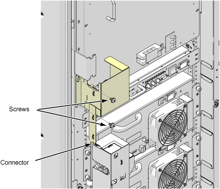
Disconnect connector and remove Water Leak sensor tray for RF Amp by removing 2 screws.
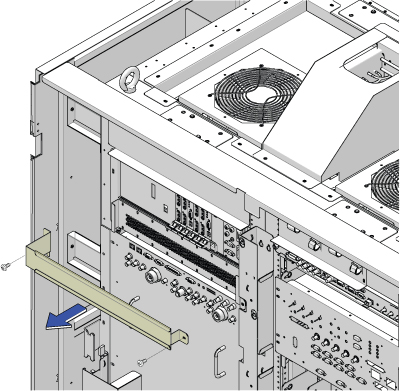
Remove bracket above the RF Amp by removing two screws.
Figure 5. Remove bracket
Note: Prior to the next step, prepare to absorb any leakage from the coolant lines with a towel in hand as the line is connected. Do not allow leakage to fall on white leak sensor strips located in cabinet in located in front and under RF amplifier.
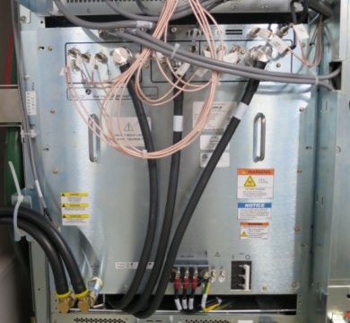
Disconnect the cables on the front of the Dual Drive RF Amp, and disconnect the coolant lines.
Figure 6. Disconnect the cables
Carefully move the cables and lines to the side of the cabinet, allowing the surrounding area to be free from any obstruction of movement for when the amplifier will be pulled out.
Figure 7. Move the cables and lines
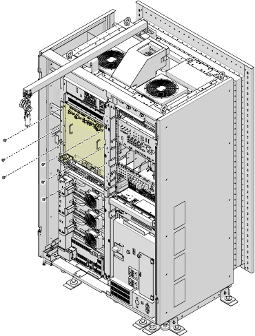
Unscrew the six attachment screws.
Figure 8. Dual Drive RF Amp Attachment Screws
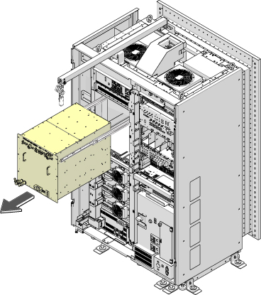
Using the two front handles, carefully slide out the Dual Drive RF Amp unit.
Figure 9. Slide Out Dual Drive RF Amp
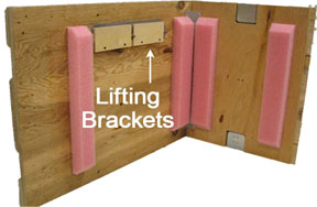
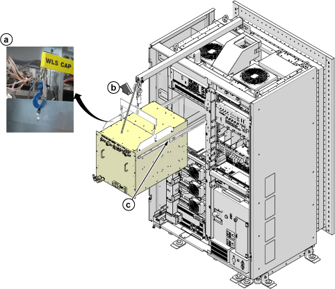
Attach the lifting brackets to both sides of the Dual Drive RF Amp. The lifting brackets can be found in the Dual Drive RF Amp FRU crate. The attachment screws are captive screws and remain with the lifting brackets.
Do not place any part of body under the replacement part to avoid the crush caused by accidental fall of the object.
Also, do not flip the angle of lifting chain over 15 degree to mitigate the risk of accident.
Perform the following steps.
Hook the winch and spreader bar from the hoist kit to the lifting bracket.
Ratchet the winch to tighten the chain.
Press the release tabs in on each side out the RF Amp.
Figure 12. Lifting Brackets with Seated Hook
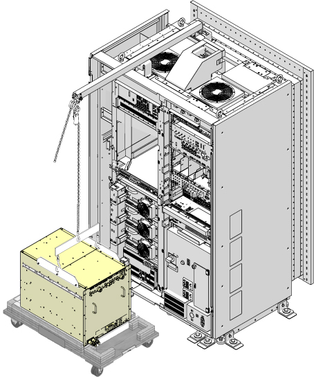
Remove the top of the wooden crate and turn it on its base.
Ratchet the winch to lower the Dual Drive RF Amp into the package.
Figure 13. Lower the Dual Drive RF Amp
Remove the hook from the lifting bracket.
Unscrew the lifting brackets from the sides of the Dual Drive RF Amp.
Roll the removed Dual Drive RF Amp to the side.
Remove the center sections of the FRU crate.
Bring the FRU to the front of the cabinet.
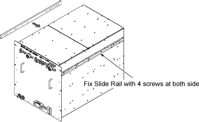
Attach the slide rails to the FRU.
Figure 14. Attach the slide rails
Attach the lifting brackets to the sides of the new amplifier.
Install Dual Drive RF Amp by the reverse order of the removal.
Connect the all of the cables and coolant lines to the Dual Drive RF Amp.
Figure 15. Cable connection
Disassemble the Hoist kit.
Restore ISC.
Finalization
Notice
The RF Amp may be damaged if power is on without coolant inside. To avoid this situation, set the RF Amp Breaker to OFF Position before power ON for new FRU.
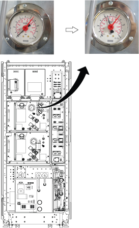
Set the RF Amp Breaker to OFF Position. Figure 16. RF Amp Breaker OFF

 Note: If the service area is narrow, do the same for right front cover.