Power On Sequencing 1 completed (ISC main breaker on; cabinet, system cooling, ICN/ICE, and host sub breaker on; and other sub breaker off.
Table 1. Safety
Warning
Do not ingest the coolant fluid.
The fluid is treated for bacteria and corrosion.
Fluid is not intended for human consumption.
Notice
Observe the following:
Follow the MSDS guidelines for Personal Protective Equipment (PPE).
The coolant fluid is bio-friendly and can be poured down a normal drain for disposal. Although the water is treated for bacteria and water corrosion, the levels of concentrate are safe for water and sewer system disposal.
About this task
This procedure provides instruction to properly:
Inspect the hoses and valves to ensure that they are correctly installed.
Fill the GCU and CCU tanks in the Integrated Cooling Cabinet (ICC) with a deionized water solution.
Check the valves for leaks after the pumps are activated and the fluid is circulating.
Topic ID: id_SL5472566-1199933
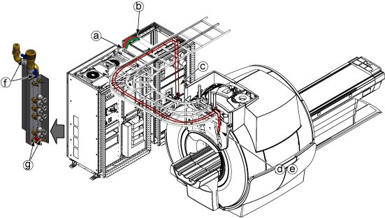
Hose and valve check
Procedure
Make sure the hose connections are secure and the valves are correctly oriented.
Hoses at ISC top.
Hoses at ICC top.
Hoses at ICC GCU rear.
Hoses at magnet rear.
Valves are opened at magnet rear.
Valves are opened at ISC water manifold.
Valves are closed at draining ports of water manifold.
Figure 1. Hose and valve check
Topic ID: id_SL2282348-1199933
Coolant fill
About this task
Do this procedure for both CCU and GCU.
Procedure
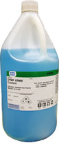
Prepare coolant bottles near ICC.
Figure 2. One coolant gallon
Note: The coolant fluid is dyed for easy detection of leaks. This also helps distinguish between a leak and any normal condensation on the hoses.
Unscrew the cap from the top of the tank of CCU.
Insert the tank funnel extension and funnel into the opening on top of the tank.
Pour the coolant into the funnel to fill the tank until the coolant level reaches near the upper limit.
(For ICC with vent valve with transparent hose Only) Vent the pump by using the existing venting valve with a transparent hose and a collecting vessel. Use the square section key to open/close the venting valve. Let the valve open as long as no more air (bubbles) appears.
Note: Vent valve with transparent hose is removed from GCU/CCU after end of Q4, 2017 per VCP with engineering analysis. No operation is needed if not exist.
Repeat Step 4 and Step 5 till the water level in tank seems to be stable and no more air bubbles appear.
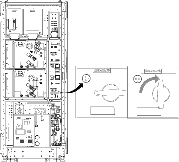
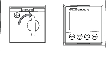
Start the pump by turning the switch of CCU at control unit and observe the water level at the tank.
Figure 5. Start the pump
Note: If the red LED is lit at control box main breaker, it is because the ICC power cable phase is wrongly connected. Refer to ICC Power Phase Error for troubleshooting.
If the water level falls rapidly, stop operation of pump and check for leakages.
If the water level falls slowly, refill water during operation until the water level stays on the mark of the filling level indication.
Make sure there is no leakage.
If CCU switch is tripped, pour the coolant into the funnel to fill the tank until the coolant level reaches near the upper limit.
Repeat Step 2 to Step 4 until CCU switch will not be tripped.
Pour the coolant into the funnel to fill the tank until the coolant level is within green area.
Remove air bubbles using the following steps.
Turn off the switch of CCU at control unit.
Vent the pump by using the existing venting valve with a transparent hose and a collecting vessel. Use the square section key to open/close the venting valve. Let the valve open as long as no more air (bubbles) appears.
The GCU pump may trip more than 30 times because the hose routing is very long. Continue turning on the switch until the coolant flows without tripping.
Turn on switches for patient blower and body coil blower on the ICC.
Finalization
When finished filling the tanks with coolant, place the funnel and tank funnel extension at the top opening of the ICC.
Keep any unused coolant for future use.
After the procedure is completed, view the hose connections closely to check for any leaks.
Check the hoses a second time after a few days (during installation) for any possible leaks.

 Note: The coolant fluid is dyed for easy detection of leaks. This also helps distinguish between a leak and any normal condensation on the hoses.
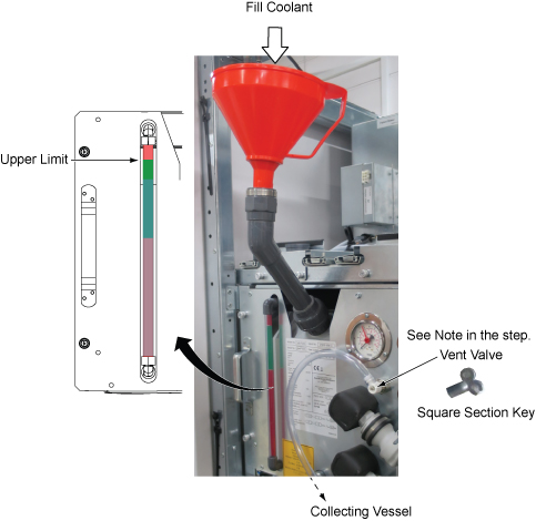
 Note: If the red LED is lit at control box main breaker, it is because the ICC power cable phase is wrongly connected. Refer to ICC Power Phase Error for troubleshooting.