Before putting weight on the hoist chain, be sure that
the links are aligned properly. This will help keep the chain from
binding up, or becoming kinked, which is nearly impossible to correct
when the chain is under tension.
CAUTION
Perform the proper Lockout/Tagout (LOTO) procedure for
the type of replacement being performed. The cabinet should not have
any power as you are assembling and using the hoist kit.
Topic ID: id_SL14184525-1179504
Hoist Base Installation
Topic ID: id_SL14184526-1179504
Hoist Base Installation for ISC
Procedure
Install ISC front hut brackets with four screws per each on
front top frame.
Figure 1. ISC front hut bracket
Topic ID: id_SL14184533-1179504
Hoist Base Installation for ICC
Procedure
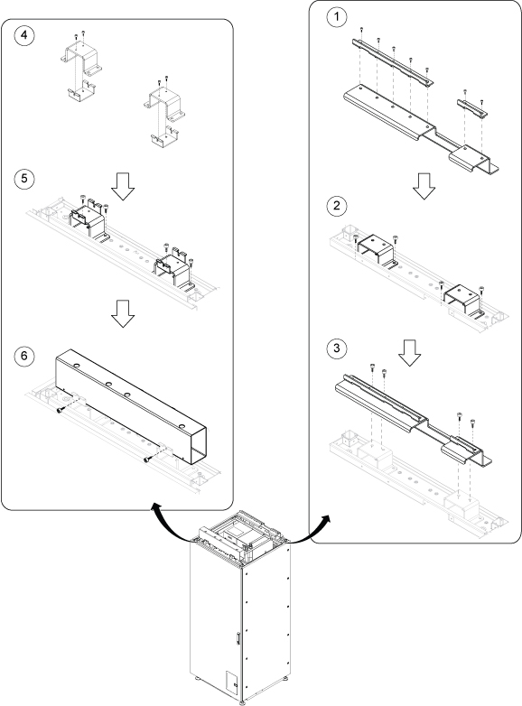
Assemble ICC RAER TABLE BRACKET (5554986), HOIST REAR BRACKET
Long (5554765) and HOIST REAR BRACKET short (5554764) with 7 screws.
Install ICC Rear hut bracket (5548602) with two screws per each.
Install assembly onto Rear hut bracket with four screws.
Assemble front base bracket (5548593) and ICC Front hut bracket
(5548602) with two screws per each.
Install assembly onto front top frame with two screws per each.
Install Support Tube (5548592) with two screws.
Note:
Support Tube (5548592) is stored behind ICC front cover.
Figure 2. Hoist Base Installation for ICC
Topic ID: id_SL14184541-1179504
Hoist Beam Setup
Procedure
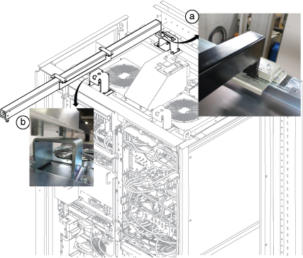
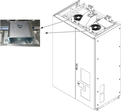
Open ISC door.
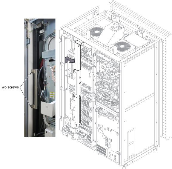
Loosen two screws and lift up the Main Lifting Beam to remove
it.
Figure 3. Main Lifting Beam
Note:
Main Lifting Beam setup position depends on the replacement
FRU location.
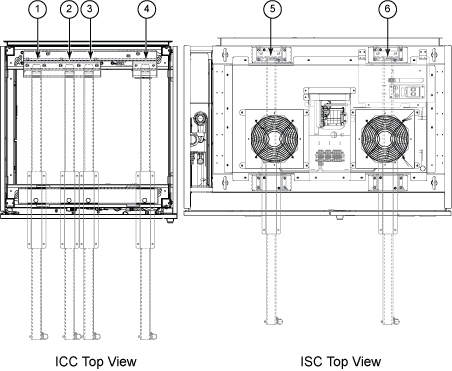
Figure 4. Main Lifting Beam setup position
Position
Lifting Component
1
Patient Blower
2
GCU, CCU
3
Body Coil Blower
4
ICC Control Unit
5
RF Amp, SSSA, SSSPS
6
Driver Module
Setup the Main Lifting Beam into the brackets.
Slides the hook plate into the rear bracket.
Insert the locking projection into the hole of front bracket.
Figure 5. Remove Support Bracket assembly
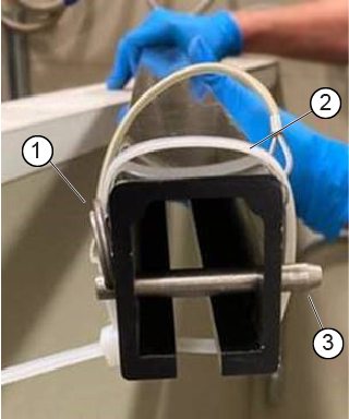
Inspect the ball bearing in the locking pin to confirm it is operating correctly and is not worn.
Figure 6. Hoist locking pin
1
Locking pin ring
2
Tie wrap
3
Ball bearing
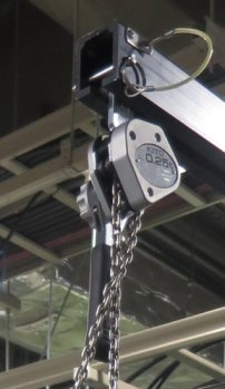
Insert the hoist assembly into the front end of hoist rail,
and then insert a locking pin into the hole of front rail. This locking
pin prevents the hoist assembly from sliding out of the rail.
Figure 7. Insert the hoist assembly and lock
Secure the locking pin ring with a tie wrap to keep it in place.
Important: This step will make sure the locking pin cannot slide out while lifting a component.
Topic ID: id_14966627
Finalization
Procedure
After replacement is completed, restore it by reverse order.

 Note:
Note: