
- SIGNA™ Hero 3.0T Service Methods
- 5852800-8EN Revision 1.0
- 00000018WIA306D0E20GYZ
- id_131062973.1
- Jul 13, 2021 6:28:47 PM
Draining Operation before replacing RF Amp, SSSA, or SSSPS Replacement
Prerequisites
| Required persons | Preliminary requirements | Procedure | Finalization |
|---|---|---|---|
| 1 | Not Applicable | 30 minutes | Not Applicable |
| Item | Quantity | Effectivity | Part number | Manufacturer |
|---|---|---|---|---|
| Coolant Tank | 1 | - | - | - |
| Hand Pump | 1 | - | - | - |
| ||||
| Condition | Reference | Effectivity |
|---|---|---|
|
System Main Breaker is OFF. Refer to ISC PDU Main Breaker LOTO Procedure. | - | - |
Procedure
- Disconnect connector and remove Water Leak sensor tray for RF
Amp by removing screw.
Figure 1. Water Leak sensor tray removal 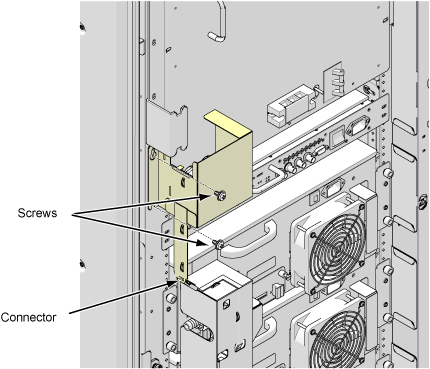
- Disconnect all of Quick Disconnect to Water Manifold and RF
Amp
Figure 2. 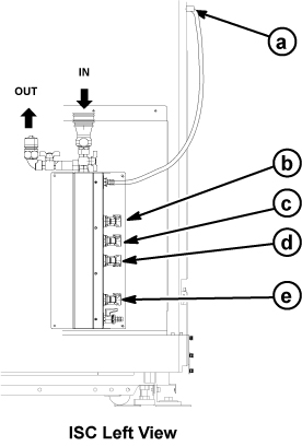
a RF Amp b SSSA (X) c SSSPS d SSSA (Y) e SSSA (Z) - Disconnect two leak sensor connectors.
Figure 3. two leak sensor connectors 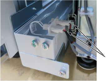
- Slide Water Manifold Plate.
- Loosen screws.
- Slide out Water Manifold assy.
Figure 4. Slide Water Manifold Plate 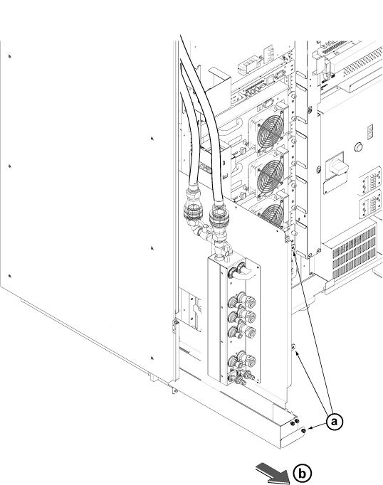
- Perform the following steps.
- Close the Manifold Valves.
- Set the drain hoses to the draining nipples and inset the other side into coolant tank.
- Open the draining valves.
Figure 5. Open Drain Valve 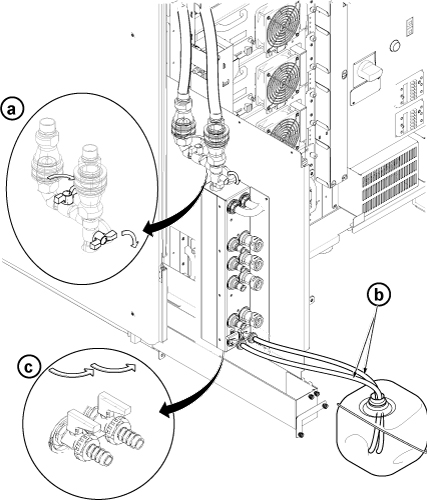
- Perform the following steps.
- Push Water Manifold Assy a little.
- Connect the Quick disconnect connectors for replacement module.
Figure 6. Quick disconnect connectors (Example) 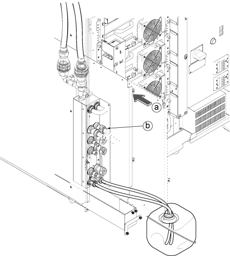
- Perform the following steps.
- Connect hand pump to one of the hose. Then, push out the coolant in the replacement module.
- Connect pump to the other hose of and insert the remaining hose to the tank. Then, push out the coolant.
Figure 7. Setup and push out coolant 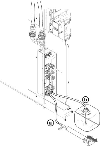
- Perform the following steps.
- Close drain valves.
- Remove the hoses from draining nipples.
Figure 8. Close Drain Valve 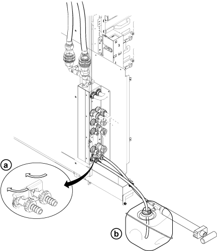
Finalization
- After Replacement is done, restore the water manifold.
- Open Water Manifold Valves
- Restore Water Manifold Plate.
- Restore Quick Disconnect connectors.
Figure 9. Restoration 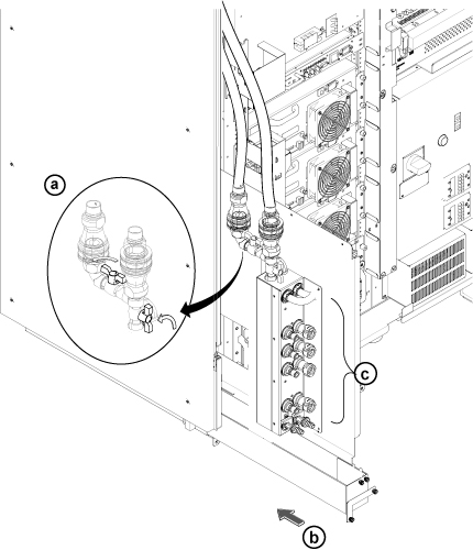
- Restore water leak sensor tray. Do not forget to connect sensor cables.