- SIGNA™ Hero 3.0T Service Methods
- 5852800-8EN Revision 1.0
- 00000018WIA309E9230GYZ
- id_156675231.7
- Jul 13, 2021 4:27:36 PM
ISC Cabinet Coolant Flushing Procedure
Prerequisites
| Required persons | Preliminary requirements | Procedure | Finalization |
|---|---|---|---|
| 1 | Not Applicable | 60 minutes | 20 minutes |
| Item | Quantity | Effectivity | Part number | Manufacturer |
|---|---|---|---|---|
| Convert Coupler BPV353 to NS6D10008 | 1 | - |
5732378 | - |
| DVMR Drain Kit | 1 | - |
3269683 | - |
| Coolant Tank | 1 | - |
| - |
| Item | Quantity | Effectivity | Part number | Manufacturer |
|---|---|---|---|---|
| Towel | As required | - | - | - |
| ||||
System Power OFF and Confirmation
Procedure
- Confirm the followings.
- CCU pressure meter (black meter) is at zero.
- ICC Control Unit TCU display is OFF.
Figure 1. Confirmation 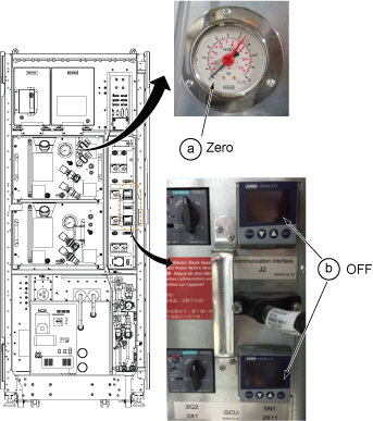
Flushing Procedure for 3 axis SSSA and SSSPS
Procedure
- Connect Convert Coupler (BPV353 to NS6D10008) to DVMR pump.
Figure 2. Convert Coupler Connection 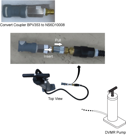
- Remove RF Amp Leak Sensor tray per following steps.
- Disconnect two connectors for RF Amp leak sensor.
- Loosen two screws.
- Move up a little and remove RF Amp Leak sensor tray.
Figure 3. Remove RF Amp Leak Sensor tray 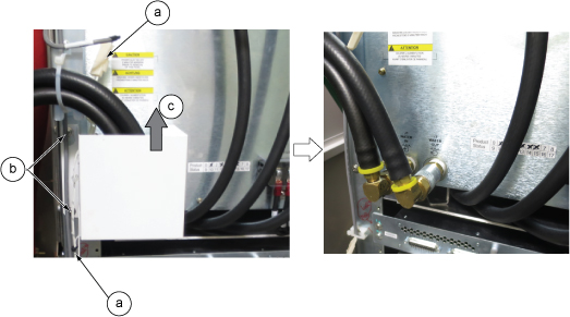
- Close Manifold top valve for supply coolant.
Figure 4. Close valve for supply coolant 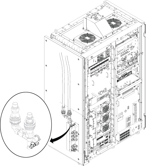
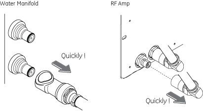
- Disconnect all supply hose per following steps.
Notice
Hold a towel in one hand below the hose connector and disconnect supply hose for RF Amp.Notice - Disconnect the all supply hoses to the SSSD at the water manifold.
Figure 5. Disconnect all supply hose 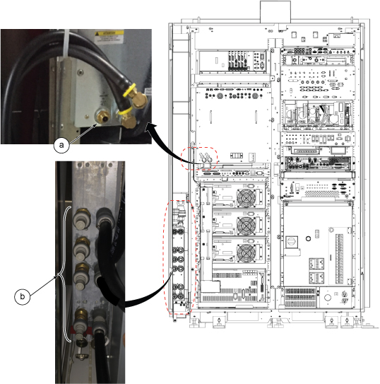
- Setup for flushing as following steps.
- Connect drain hose to the supply side of drain port.
- Insert drain hose to flexible tank.
Figure 6. Setup 1 for flushing 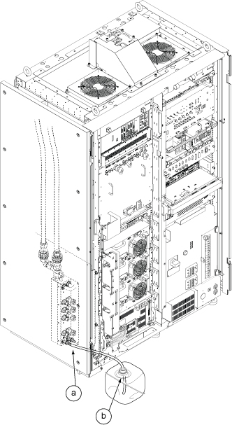
- Setup for flushing as following steps.
- Connect Pump hose to Port 1.
- Open the Drain Valve.
Figure 7. Setup 2 for flushing 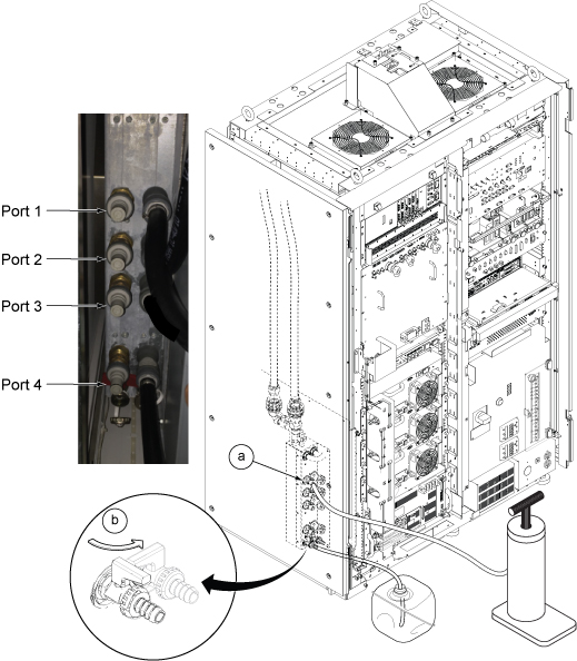
- Open Manifold top valve for 30 sec to fill the coolant in manifold. Then, close it again.
Figure 8. Valve control 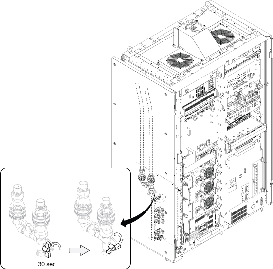
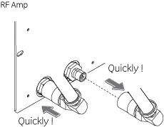
Flushing Procedure for RF Amp
Procedure
- Remove Convert Coupler (BPV353 to NS6D10008) from DVMR pump.
Figure 9. Remove Convert Coupler 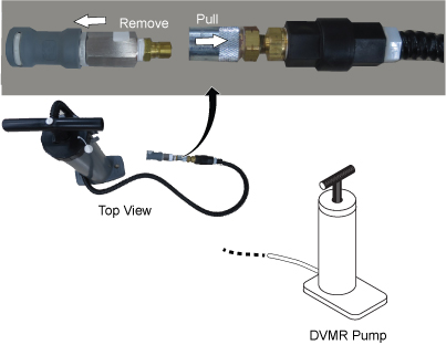
- Setup as following steps.
Notice
Hold a towel in one hand below the hose connector and connect supply hose for RF Amp.Notice - Disconnect return hose of RF Amp .
- Connect Pump hose to return port of RF Amp.
- Open Drain valve
Figure 10. Setup 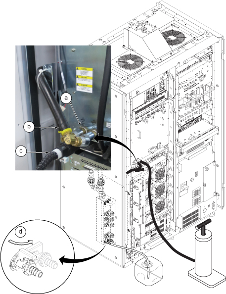
Restoration
Procedure
- Open Manifold top valve.
Figure 11. Open Manifold top valve 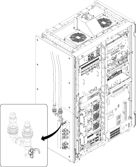
Finalization
Procedure
Set the RF Amp Breaker to OFF Position.Notice Figure 12. RF Amp Breaker OFF 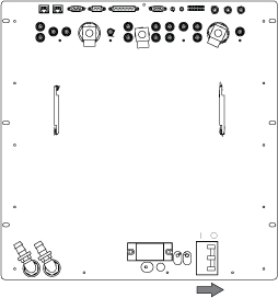
- Wait till pressure meter (black meter) of CCU moves for about 40 seconds.
Figure 13. pressure meter 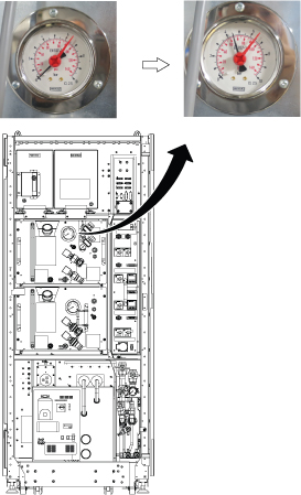
- Turn the RF Amp Breaker ON
Figure 14. RF Amp Breaker ON 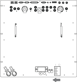
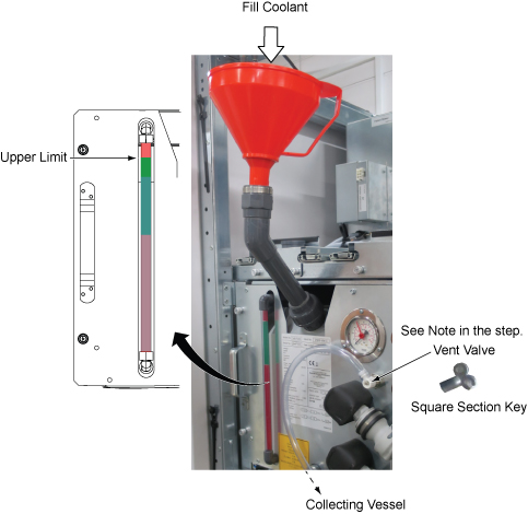
- Refill Coolant. Refer to Refill Coolant .Note: Reuse the drained coolant using the red funnel. Note that the funnel has a filter to exclude the unaccepted particles.Vent valve with transparent hose is removed from GCU/CCU after end of Q4, 2017 per VCP with engineering analysis. No operation is needed if not exist.
Figure 15. Restore Coolant