
- SIGNA™ Hero 3.0T Service Methods
- 5852800-8EN Revision 1.0
- 00000018WIA3055C230GYZ
- id_156672891.11
- Jan 26, 2022 1:41:02 AM
SSSPS Replacement
Prerequisites
| Required persons | Preliminary requirements | Procedure | Finalization |
|---|---|---|---|
| 1 | Not Applicable | 120 minutes | 15 minutes |
| Item | Quantity | Effectivity | Part number | Manufacturer |
|---|---|---|---|---|
| Standard Tool | 1 | - | - | - |
| Hoist Service Kit | 1 | - |
5196226 | - |
| Item | Quantity | Effectivity | Part number | Manufacturer |
|---|---|---|---|---|
| SSSPS | 1 | - |
Refer to FRU Manual | - |
| ||||||||||||
| Condition | Reference | Effectivity |
|---|---|---|
|
System Power must be turned OFF. Refer to LOTO for ISC. | - | - |
Procedure
- Confirm that there is no input voltage at the terminal of SSSPS using DVM.
Figure 1. Voltage Check 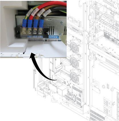
- Remove left front cover per following steps.
- Open left front cover and remove a screw to disconnect GND cable.
- Unlock the cover.
- Lift up and remove the cover.
Figure 2. Cover removal 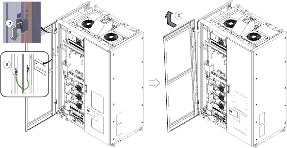 Note: If the service area is narrow, do the same for right front cover.
 - Perform the following steps.
- Disconnect two connectors.
- Remove six screws.
- Remove Leak sensor assy.
Figure 3. Remove Leak Sensor 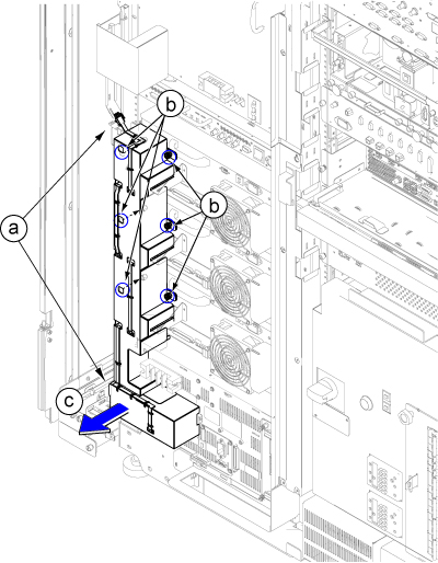
Disconnect the IN and OUT quick couplers of SSSPS from the water manifold.Warning Figure 4. Water Manifold Socket Order 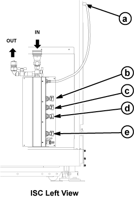
a RF Amp b SSSA (X) c SSSPS d SSSA (Y) e SSSA (Z) Note: When disconnecting the quick couplers, move the couplers in parallel not to damage it.
Connect the IN and OUT of quick coupler.CAUTION Figure 5. Water Manifold 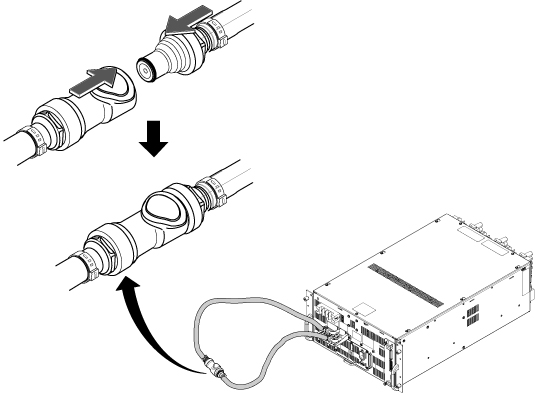
- Perform the following steps.
- Disconnect all cables.
- Remove two M5x40mm screws installed at both side.
- Loosen 4 screws which are tightening SSSPS front panel to the chassis.
- Screw two M5x40mm screws at two push out screw holes to push the SSSPS to the chassis and gradually slide it out from Cabinet.
Figure 6. Slide SSSPS out 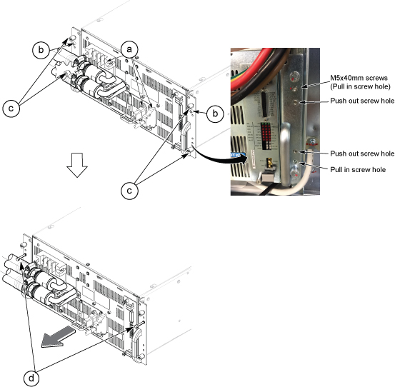
- Install Hoist Brackets to SSSPS.
Figure 7. Hoist Brackets 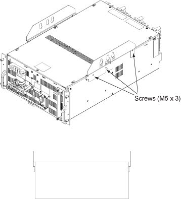
- Perform the following steps.
- Hook the winch and spreader bar from the hoist kit to the lifting bracket named “SSSPS”
- Ratchet the winch to tighten the chain.
- Press the release tabs in on each side and remove the 2nd slide rail from 1st slide rail.
Figure 8. Hoist Operation 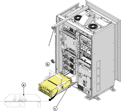
Finalization
-
Set the RF Amp Breaker to OFF Position.Notice 
Figure 9. RF Amp Breaker OFF 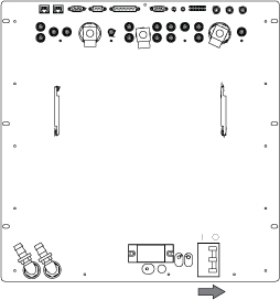
- Restore the System Power. Refer to Removing LOTO - ISC
- Wait till pressure meter (black meter) of CCU moves for about 40 seconds.
Figure 10. Pressure meter 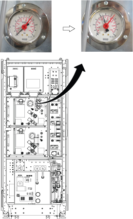
- Turn the RF Amp Breaker ON
Figure 11. RF Amp Breaker ON 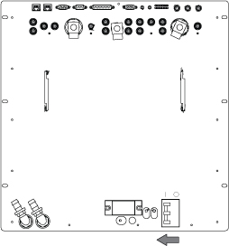
- Refill Coolant. Refer to Refill Coolant.
- Perform Doing DQA calibration.
- Perform check scan.