
- SIGNA™ Hero 3.0T Service Methods
- 5852800-8EN Revision 1.0
- 00000018WIA30B0C230GYZ
- id_156670691.12
- Jul 13, 2021 4:27:37 PM
Gradient Filter Replacement
Prerequisites
| Required persons | Preliminary requirements | Procedure | Finalization |
|---|---|---|---|
| 1 | Not Applicable | 60 minutes | 15 minutes |
| Item | Quantity | Effectivity | Part number | Manufacturer |
|---|---|---|---|---|
| Non Magnetic Tool Set | 1 | - | - | - |
| Digital volt meter (DVM) with alligator clip leads | 1 | - | - | - |
| Hoist Service Kit | 1 | - |
5196226 | - |
| Adjustable wrench, 8 inch, titanium | - | - |
5109896-2 | - |
| Item | Quantity | Effectivity | Part number | Manufacturer |
|---|---|---|---|---|
| Gradient Filter | 1 | - |
Refer to FRU Manual | - |
| ||||
| Condition | Reference | Effectivity |
|---|---|---|
|
PDU must be turned OFF. Refer to ISC PDU Lockout / Tagout. | - | - |
Procedure
- Remove left front cover per following steps.
- Open left front cover and remove a screw to disconnect GND cable.
- Unlock the cover.
- Lift up and remove the cover.
Figure 1. Cover removal 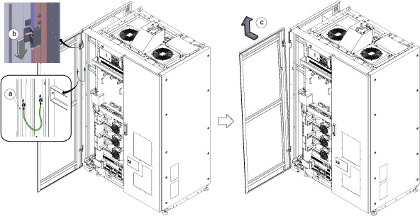 Note: If the service area is narrow, do the same for right front cover.
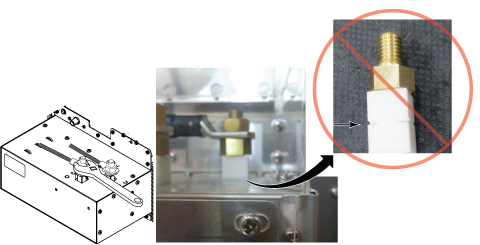
Disconnect the IN and OUT quick couplers of corresponding SSSA from the water manifold.Warning Figure 2. Water Manifold Socket Order 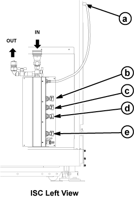
a RF Amp b SSSA (X) c SSSPS d SSSA (Y) e SSSA (Z) - Connect the IN and OUT of quick coupler, and tie the hose as illustration.
Figure 3. Quick coupler 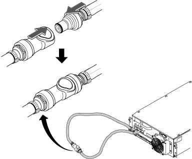
- Perform the following steps.
- Disconnect two connectors.
- Loosen six screws.
- Remove Leak sensor assy.
Figure 4. Leak Sensor 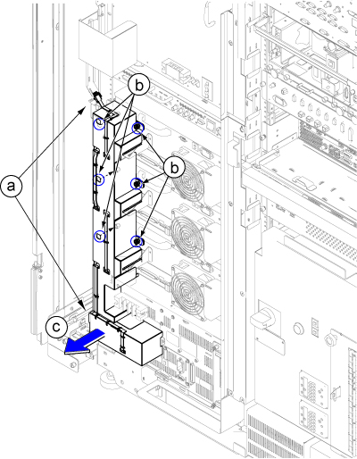
- Loosen fixing screws and remove ISC PW Cover by lifting up a little.Note: If furnished closet door prevents from removing, the PW cover can be separated in two pieces by removing 6 screws at center.
Figure 5. ISC PW Cover 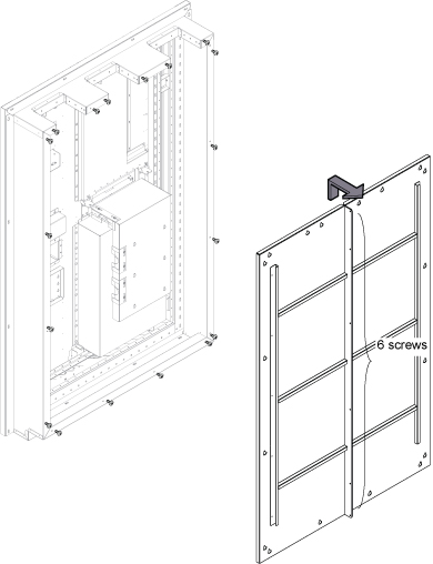
- Remove Gradient Cable Cover per following steps.
- Loosen 12 screws.
- Lift up a little and remove the Gradient Cable Cover.
Figure 6. Gradient Cable Cover 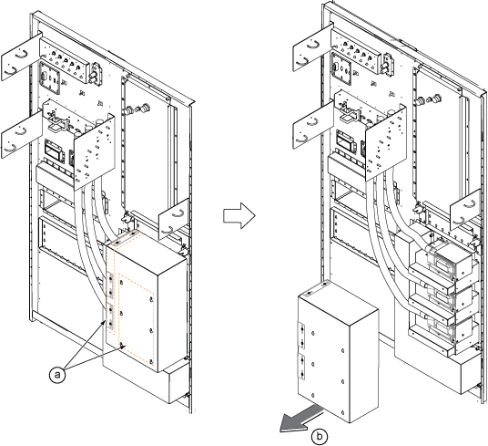
- Remove three Gradient Filter Covers by removing two screws per each cover.
Figure 7. Gradient Filter Covers 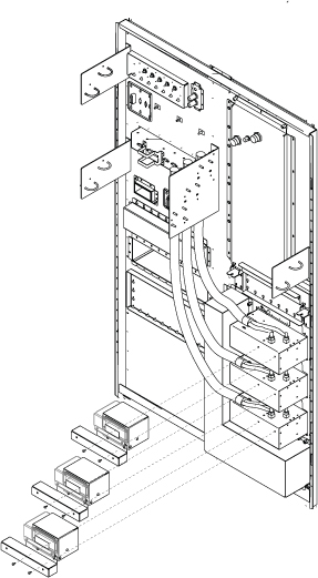
- Perform the following steps.
- Disconnect Gradient Cable using 8 inch adjustable wrench.
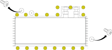
- Remove 17 screws fixing G-Filter and Pen Panel.
Fix G-Filter to SSSA using two connection screws.Notice 
Figure 8. Gradient Filter Preparation 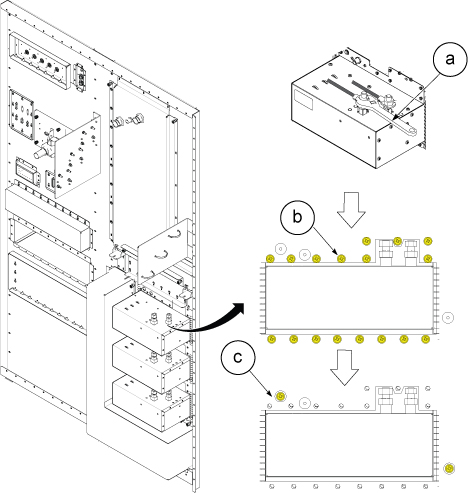
- Disconnect cables and Loosen 4 screws from SSSA.
- Disconnect the all connectors and terminals from front panel of SSSA.
- Loosen 4 screws tightening SSSA front panel to the chassis.
- Withdraw SSSA.
Figure 9. Cables and 4 Screws 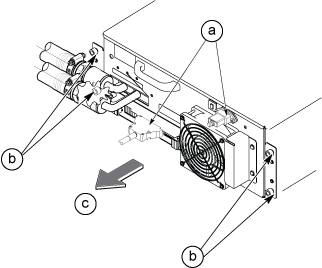
- Install the hoist brackets to the chassis of SSSA with 6 screws.
Figure 10. Hoist Brackets 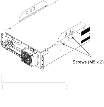
- Perform the following steps.
- Hook the winch and spreader bar from the hoist kit to the lifting bracket named “SSSA WITH FILTER”.
- Ratchet the winch to tighten the chain.
- Press the release tabs in on each side and remove the 2nd slide rail from 1st slide rail.
Figure 11. Hoist Operation 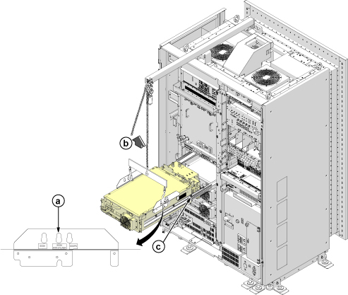
- Use the hoist and slowly lower the SSSA Chassis to the floor.Note: When lowering the SSSA Chassis, it may be easier to rotate SSSA 90 degree as following illustration.
Figure 12. Hoist Operation 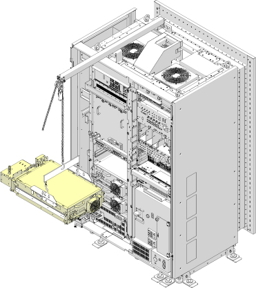
- Remove gradient filter.
- Remove two screws.
- Slowly pull out Gradient Filter from SSSA.
Figure 13. Remove Gradient Filter 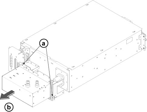
Notice
Install SSSA by reverse order of removal.Notice  Note: Make sure to connect all cables.
Finalization
- Restore the Power. Refer to Removing LOTO - ISC.
- Perform DQA II.
- Perform check scan.