
- SIGNA MR355 / SIGNA MR360
- Service Manual
- 5856356-3EN Revision 5.0
- Basic Service Documentation. Copyright General Electric Company.
- 00000018WIA30824630GYZ
- id_20113192.1
- Mar 3, 2021 3:46:54 AM
Replacing the leak sensors
Procedure
- Disconnect cable to leak sensor1 or leak sensor2.
There are two leak sensor routes. This test checks that the each sensor route is operational. They are both connected to J6 of cabinet monitor.
- Leak Sensor 1 (Blue line): Connected to J6 of cabinet monitor
- Leak Sensor 2 (Red line): Connected to J6 of cabinet monitor
Figure 1. Leak sensor connections 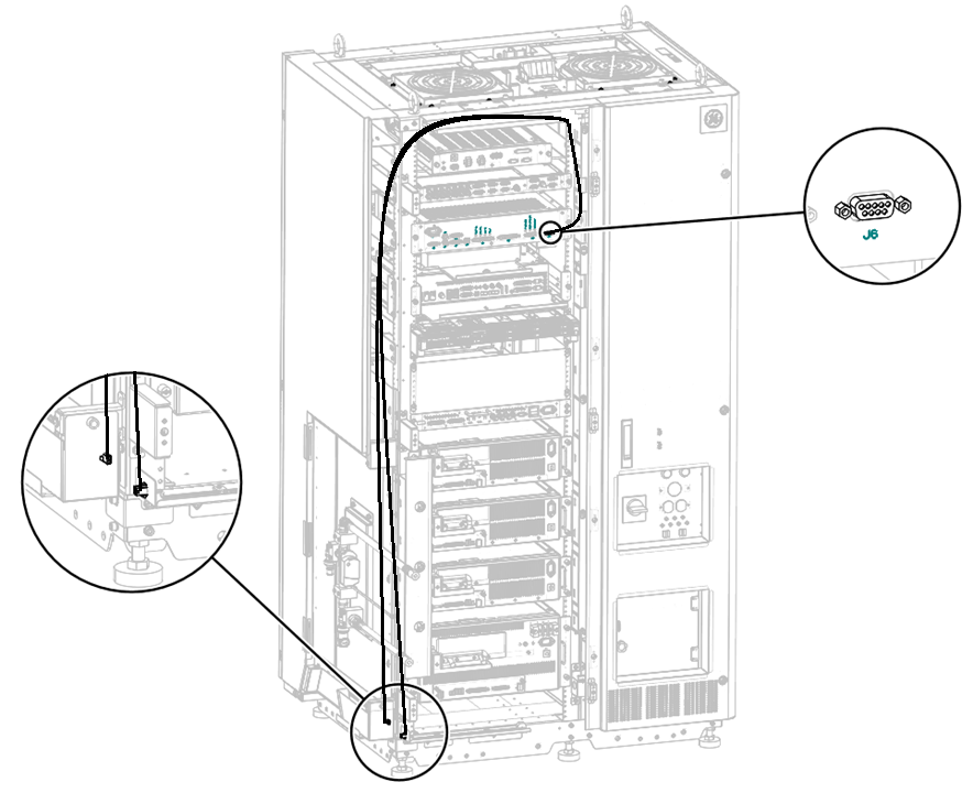
- Replace the leak sensor1.
- Remove screw from leak sensor1.
- Slide out leak sensor1.
- Install the new leak sensor by reverse order above.
Figure 2. Removing leak sensor1 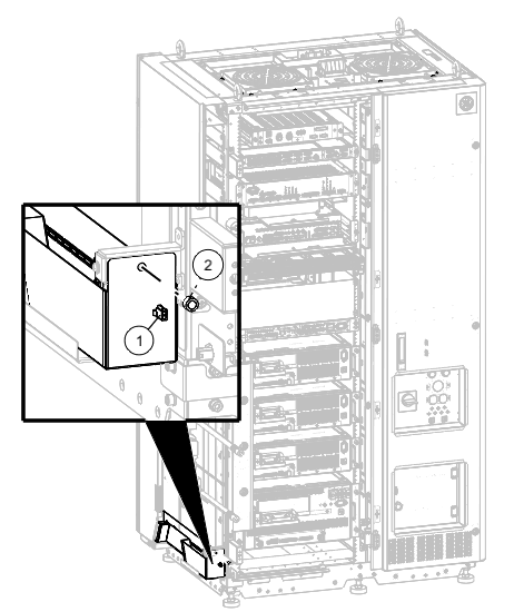
1 Leak sensor1 connector 2 Screw - Replace the leak sensor2.
- Remove two screws from leak sensor2.
- Install the new leak sensor and secure the screws.
Figure 3. Removing leak sensor2 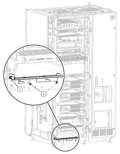
1 Leak sensor2 connector 2 Screws