
- SIGNA MR355 / SIGNA MR360
- Service Manual
- 5856356-3EN Revision 5.0
- Basic Service Documentation. Copyright General Electric Company.
- 00000018WIA30481030GYZ
- id_131061981.6
- Jul 5, 2019 10:46:04 PM
PS for LED Power Box
Prerequisites
| Required persons | Preliminary requirements | Procedure | Finalization |
|---|---|---|---|
| 1 | Not Applicable | 30 minutes | 15 minutes |
| Item | Quantity | Effectivity | Part number | Manufacturer |
|---|---|---|---|---|
| Standard Tool | 1 | - | - | - |
| Item | Quantity | Effectivity | Part number | Manufacturer |
|---|---|---|---|---|
| DC Power Supply Tray Assembly | 1 | - |
5351003 | - |
| AC-DC power supply, 24V | 1 | - |
5803655 | - |
| LED box DCPS tray without 24V PS | 1 | - |
5803648 | - |
| ||||
| Condition | Reference | Effectivity |
|---|---|---|
|
System Power must be turned OFF. Refer to System Cabinet PDU Main Breaker LOTO Procedure. | - | - |
About this task
Overview
Location of each Power Supply is as following illustration
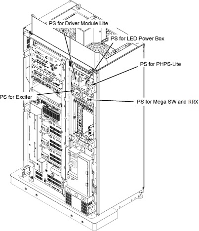
DC Power Supply Tray Assembly Replacement
About this task
Procedure
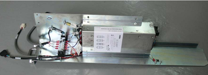
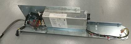
Remove the PS for LED Power Box tray from System Cabinet.Notice Figure 3. PS for LED Power BOX 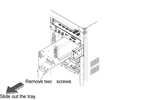
AC-DC Power Supply Replacement
About this task
Procedure
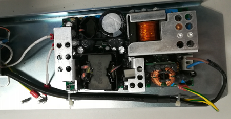
- Remove PS pin connectors.
Figure 5. Remove PS pin connectors 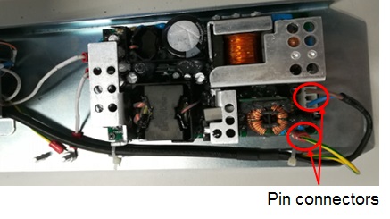
- Remove 4 screws (1007–m3c008–14).
Figure 6. Remove screws 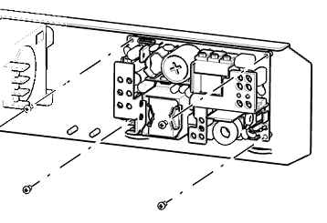
- Remove the white cable by removing the two screws.
Figure 7. Remove screws 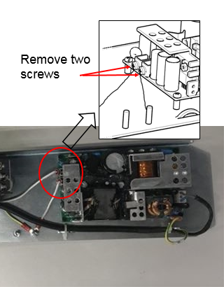
- Restore power supply by reverse order of removal.Note:Please note below marking (+24V, GND) when restored the cables.
Figure 8. Marking 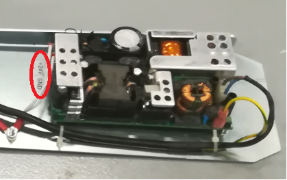
DCPS Tray Replacement
About this task
Procedure
- Remove the AC-DC power supply, refer to AC-DC Power Supply Replacement.
- Replace the DCPS tray.
- Restore AC-DC power supply.
- Restore the whole assembly to system cabinet by reverse order of removal.
Finalization
Procedure
- Restore the Power. Refer to System Cabinet PDU Main Breaker LOTO Procedur.
- Run one head or body scan.