Prerequisites
Table 1. Personnel requirements| Required persons | Preliminary requirements | Procedure | Finalization |
|---|
| 1 | Not Applicable | 30 minutes | 15 minutes |
Table 2. Tools and test equipment| Item | Quantity | Effectivity | Part number | Manufacturer |
|---|
| Standard Tool | 1 | - | - | - |
Table 3. Replacement parts| Item | Quantity | Effectivity | Part number | Manufacturer |
|---|
| PS for Driver
module Lite (Refer to Illustrated parts) | 1 | - | - | - |
Table 4. Safety
| Warning |
|---|
| ELECTROCUTION HAZARD! DANGEROUS AND OR FATAL VOLTAGES ARE PRESENT IN THE ENERGIZED
CABINET. Follow loto steps as given in first section of this document
to disable and verify safe voltage levels. |
|
About this task
Location of each Power Supply is as following illustration
Figure 1. Location of Power Supply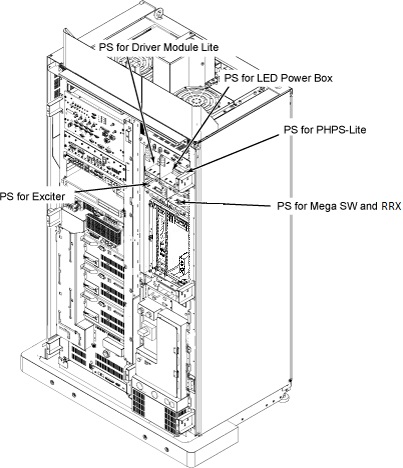
Procedure
- Remove Front Cover. Refer to SC Cover Removal
- Disconnect J20, 102, 111 and 116 connectors from front panel
of Driver Module Lite.
Figure 2. Cable Removal from Driver Module Lite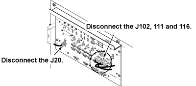
Note:
PS connectors are designed to be uniquely connected to the other end to avoid the mis-connection except Receiver and Exciter cable connectors.
- Disconnect the connectors which are routed from PS for Driver
Module Lite. If necessary, cut the tie wraps.
- Loosen 2 screws which are tightening power supply and chassis.
| Notice |
|---|
| PS Tray is tightly inserted in the bracket. Need enough pull force to remove it. |
- Remove PS for Driver Module Lite from the System Cabinet.
Figure 3. Driver Module Lite power supply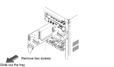
- Restore the new Driver Module Lite power supply by the reverse
order.
