- id_2019677
- Version: 3.0
- Date: Oct 23, 2019 3:17:05 PM
Removing the hydraulic rotary pump
Removes the hydraulic rotary pump from the dockable table.
Prerequisites
|

|
Procedure
- Undock the patient table and move it out of magnet room.
- Remove the lower base side covers. See Patient Table Upper and Lower Base Cover Removal.
- Raise the patient table to the full up position.
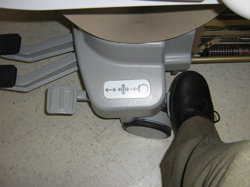
- Set the brake to keep the table stationary.
Figure 1. Caster brake
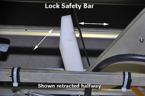
- Lower the table lock safety bar to the locked position.note: Lower the table so its weight is resting on the lock bar.
Figure 2. Lock safety bar
- Remove the base side cover from the table.
- To remove the table frame connector assembly(32 channel only), do the following:
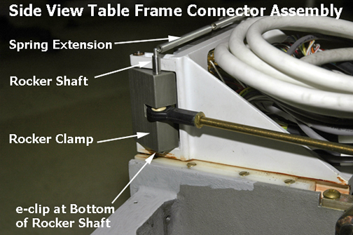
- Remove the e-clip from the bottom of each rocker shaft that holds the rocker clamp in place. If desired, remove the e-clip from the upper part of the rocker shaft above the rocker clamp.
Figure 3. Table frame connector assembly rod link
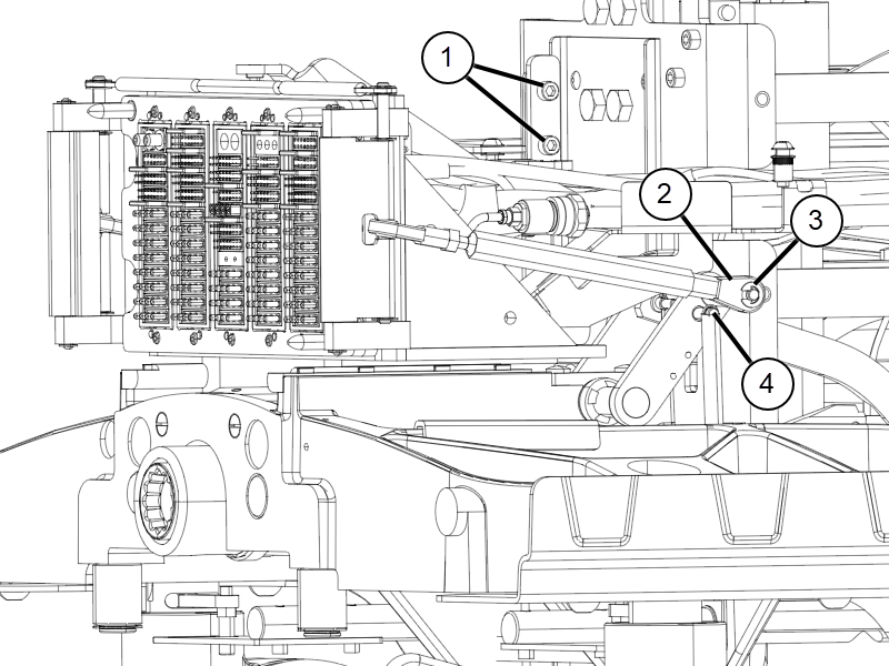
1 Bracket screws 2 Rod link 3 E-clip 4 Spring - Slide the rocker shafts up to remove.
Figure 4. Side view table frame connector assembly
- Pull the entire assembly forward to reveal the rotary pump assembly below.
Figure 5. Table frame connector assembly
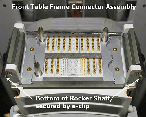
Figure 6. Table frame connector assembly
note: Before proceeding to the next step, first prepare the new hydraulic rotary pump for installation and place it within reach. Place absorbent towels underneath the work area. - Remove the e-clip from the bottom of each rocker shaft that holds the rocker clamp in place. If desired, remove the e-clip from the upper part of the rocker shaft above the rocker clamp.
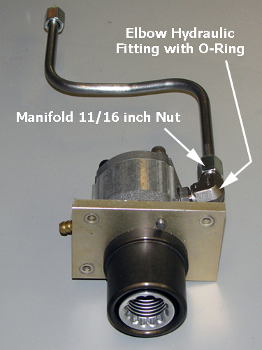
- On the right side of the pump, use an 11/16 inch open-end wrench to disconnect the manifold nut from the connector fitting .note: Use a towel as plug to stop flow of fluid.
Figure 7. Manifold pipe attached to elbow fitting on side of rotary pump
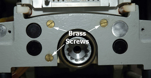
- Remove three brass screws from the lower front table base. After screw removal, the pump assembly hangs freely and should allow sufficient movement. Use care in holding the rotary pump, the brass plate, and the guide coupling in place because those components (as a unit) will fall straight down.
Figure 8. Front table base screws
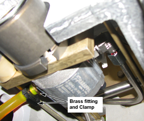
- Lower the pump assembly. Remove the plastic clamp from the transparent low-pressure hose and then remove the hose, quickly plugging the end of the hose with a thumb or a towel to minimize leaking.
Figure 9. Brass fitting and clamp