- id_12373927
- Version: 1.16
- Date: Dec 4, 2019 10:39:27 AM
Patient Table Cable Take-up and GEM MUX Box Replacement
Prerequisites
| Required persons | Preliminary requirements | Procedure | Finalization |
|---|---|---|---|
| 1 | Not Applicable | 120 minutes for any non-GEM cable track; 120 minutes for P3 ODU to MUX (GEM only); 400 minutes for PA to MUX (GEM only); 220 minutes for P2 or P4 (GEM only) | Not Applicable |
| Item | Quantity | Effectivity | Part number | Manufacturer |
|---|---|---|---|---|
| Phillips screwdriver | 1 | - | - | - |
| Flat head screwdriver | 1 | - | - | - |
| Standard Allen wrench set | 1 | - | - | - |
| Small flat head screwdriver with long shaft | 1 | - | - | - |
| Pliers | 1 | - | - | - |
| 2 x 4 x 10 in (5 x 10 x 25 cm) block of wood (or similar non-ferrous material) | 2 | - | - | - |
| Standard wrench set | 1 | - | - | - |
| Non-ferrous Phillips screwdriver | 1 | - | - | - |
| Item | Quantity | Effectivity | Part number | Manufacturer |
|---|---|---|---|---|
| Loctite 242 | 0.5 cc | - |
46-170686P1 |
- |
| Material handling gloves | 1 pair | - | - | - |
| Item | Quantity | Effectivity | Part number | Manufacturer |
|---|---|---|---|---|
| 1.5T Table Cable Track (TIP to P3 or P4) | 1 | - |
See FRU Manual |
- |
|


Overview
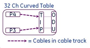
The 32-channel curved table has P3 and P4 port connectors in the table.
This procedure describes the replacement of the patient table cable take-up from the P-port connection to the table interface plate (TIP).
Figure 1. Table Diagram for Cable Track Replacement
This instruction contains the following procedures:
Removing Patient Table Cable Take-Up for 32-Channel Curved Table
Procedure
- Undock the patient table and remove it from the magnet room.
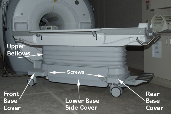
- Depending on which cable take-up (left or right) is being replaced,
remove the appropriate lower base side cover, and fasten the upper
bellows in the up position. See Patient Table Upper Bellows and Lower Base Side Cover Removal.
Figure 2. Patient Table Covers
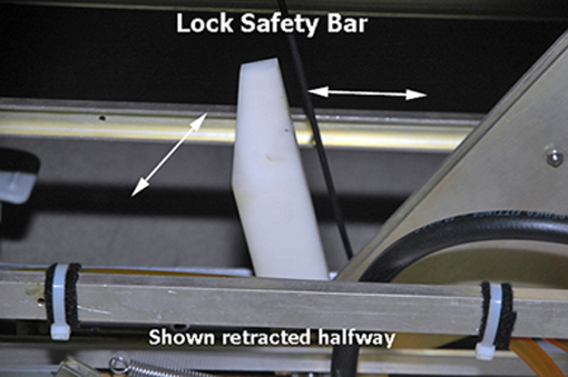
- Lower the table lock safety bar, then lower the table and verify
that its weight is resting on the safety bar.
Figure 3. Table Lock Safety Bar
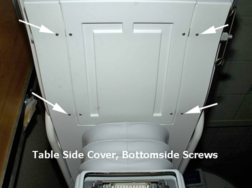
- Remove the bottom front cover (located on the front underside
of the patient table) and the right or left table side cover, depending
on which cable track is being removed.note:
When standing at the foot of the patient table facing the magnet, the P3 cable take-up is on the right side and P4 cable take-up is on the left side.
Figure 4. Bottom Front Cover
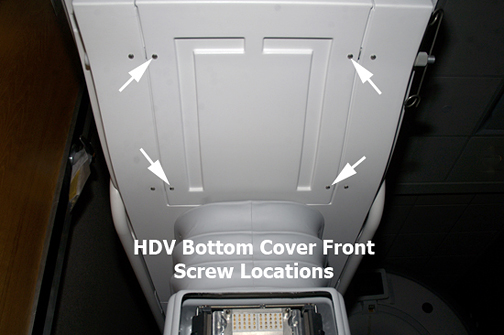
Figure 5. Bottom Screws on Table Side Cover
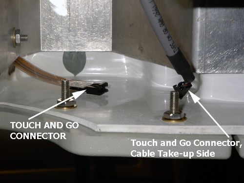
- Disconnect the gray TBL P3-J7 or P4-J7 cable from the Touch
and Go connector located in the upper left or right corner inside
the table top.
Figure 6. Touch and Go Connector
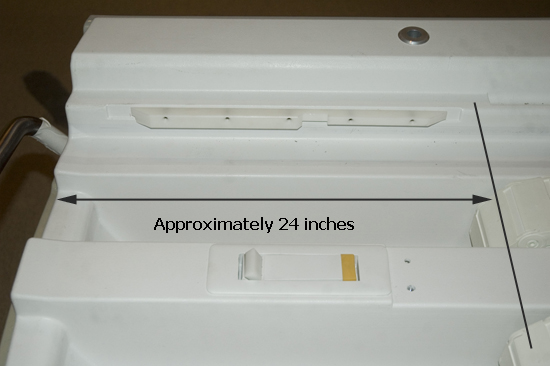
- Manually unlock the cradle, and move it forward approximately
24 in (61 cm) to clear the guide rails.
Figure 7. Guide Rail Clearance
- Prop up the rear of the cradle using two blocks of wood or similar
non-ferrous material, each approximately 10 in (25 cm) long.
Figure 8. Cradle Removal
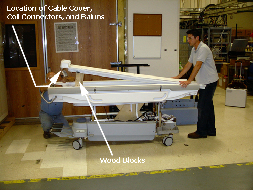
- While another person holds the front of the cradle to ensure
it does not slide off the table, use a 9/64 Allen wrench to remove
the screws in order from the cable cover, coil connector, and balun
for both cable take-ups (located on the rear underside of the cradle).note:
Although only one cable take-up is being replaced, this step requires removal of both cable take-up connections from the bottom rear of the cradle because the cradle must be removed from the patient table to access the cable take-up in the track wells.
- Remove the cradle from the patient table and set it on a flat surface.
- Depending on which take-up being replaced, go to the left or
right side of the front lower table chassis and disconnect all take-up
connectors from the rear side of the TIP.note:
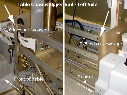
Standing at rear of the table, the right side is the P3 cable take-up, and the left side is the P4 cable take-up. To make accessing the P4 connectors on the TIP easier, remove the 3/8 inch nut and washer from the front and rear of upper chassis rail.
Figure 9. Right Side View of TIP Connectors
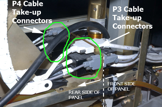
Figure 10. Removing Left Side Upper Chassis Rail
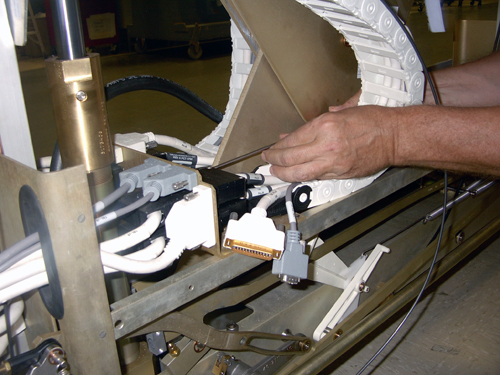
 note:
note:Be careful with the J1/J2 and J4/J5 black connectors. They use small, standard head screws that are made of lightweight aluminum and can be easily stripped.
Figure 11. Using Long Shaft Screwdriver
- notice
- To remove the main cradle latch cable, which is threaded through
the P4 take-up track, do the following:
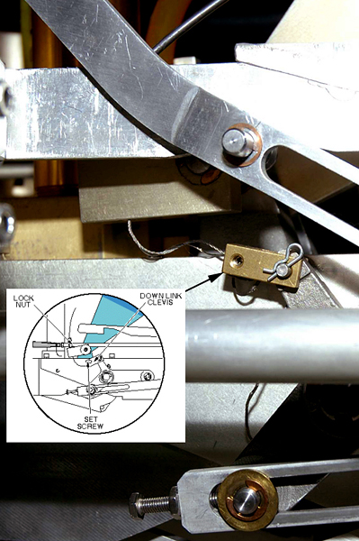
- Use a 5/64 Allen wrench to loosen the set screw at the down
link clevis, then unthread the cable.
Figure 12. Main Cradle Latch Cable Path and Down Link Clevis
- Pull cable through to clear the back side of the cable track
and underside of cable take-up lead.
Figure 13. Path of Main Cradle Latch Cable behind P4 Cable Track
- Use a 5/64 Allen wrench to loosen the set screw at the down
link clevis, then unthread the cable.
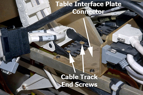
- Remove both cable track end screws from the TIP connector.
Figure 14. Cable Track End Screws
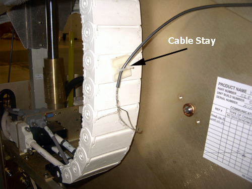
- Follow the cable track up to the underside of table top, and pull out the disconnected gray P3-J7 or P4-J7 cable that was previously disconnected.
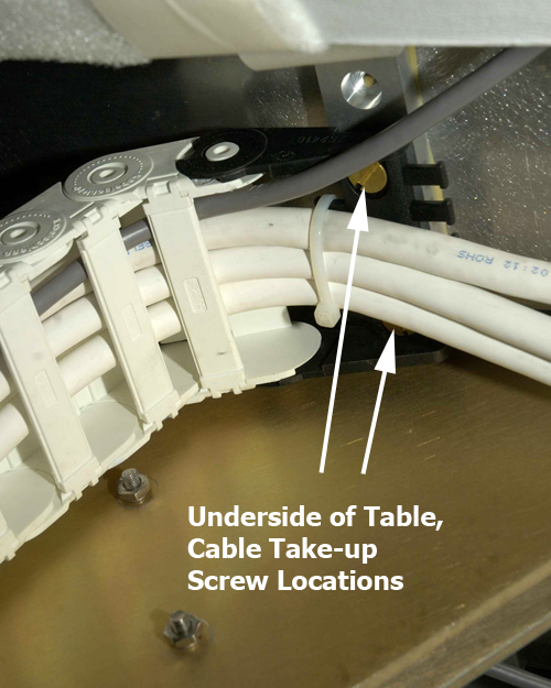
- Remove the cable take-up lead brass screws.
Figure 15. Underside of Table Top
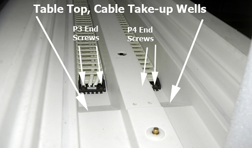
- Remove the two slotted brass screws from the cable take-up lead
in the cable well.
Figure 16. Take-Up End Screws in Table Top
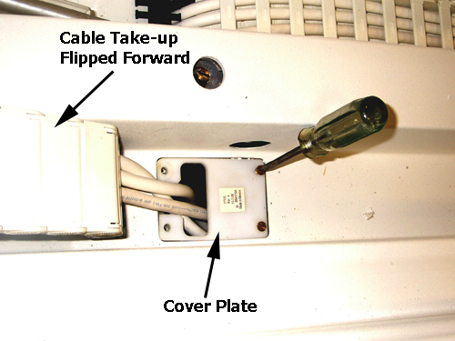
- Pull the rear of the cable take-up, lay it out in the front
of the patient table to expose the cover plate and screws, and remove
both screws.
Figure 17. Cover Plate
- To fully remove the cable take-up assembly from the patient table, feed the cable take-up assembly up through the hole in the table top.
 |
Replacing Patient Table Cable Take-Up for 32-Channel Curved Table
Procedure
- Place the new cable take-up assembly into the table cable track well, and feed the take-up through the table hole.
- Secure the cover plate with the two brass screws. (See Figure 17.)
- Lay out the cable take-up assembly to point to the rear of the patient table and allow access to the cable take-up lead.
- Secure the cable take-up lead to the cover, and replace the two brass screws.
- At the underside of the table top, secure the cable take-up lead to the table. (See Figure 15.)
- Reroute and reconnect P3-J7 or P4-J7 Touch and Go gray cable, making sure to route the cable through the two cable supports (tie wraps) before reconnecting.
- notice
- (For P4 cable take-up replacement only) Reroute and reconnect the main cradle latch cable to the down link clevis, and make appropriate adjustments at the end of this procedure to the cable according to Cradle Release Block Retraction Adjustment in Cradle/Table Release Block Adjustment.
- Reconnect all cables on the TIP.note:
Be careful with the J1/J2 and J4/J5 black connectors. They use small, standard head screws that are made of lightweight aluminum and can be easily stripped.
- Secure the cable take-up lead to the TIP with the brass screws. (See Figure 14.)
- If replacing the P4 cable take-up assembly, replace the upper chassis rail front and rear 3/8 nut and washer. (See Figure 10.)
- Place the cradle back onto the patient table, and prop it up with the two blocks of wood or similar non-ferrous material as shown in Figure 8.
- On the rear underside of the cradle, replace in order: balun, coil connector, and cable cover for each cable take-up. Remove the blocks of wood and set the cradle back onto the table top at the home position.
- Replace the front bottom and table side covers.
- Ensure that the lock safety bar is in the vertical (up) position.
- Move the patient table into the magnet room and dock the table.
- If the P4 cable take-up was replaced, make the main cradle latch cable adjustments as described in Step 7.
- Undock the patient table and use the non-ferrous Phillips screwdriver to replace the lower base side cover, then place the upper bellows in the down position.
|
Finalization
Finalization
-
Dock the patient table.
-
Confirm that the cradle release functions properly.
-
Confirm that the LPCA connects to the cradle and the cradle moves into the bore.