- id_12373792
- Version: 1.6
- Date: Jan 17, 2020 11:09:43 AM
Patient Table Caster, Wheel and Pad Replacement
Prerequisites
| Required persons | Preliminary requirements | Procedure | Finalization |
|---|---|---|---|
| 2 | Not Applicable | 15-30 mins. per caster, 10 mins. per wheel kit | Not Applicable |
| Item | Quantity | Effectivity | Part number | Manufacturer |
|---|---|---|---|---|
| Nonferrous Level | 1 | - | - | - |
| 6.5 in. Block of Wood, minimum | 1 | - | - | - |
| Nonmagnetic Service Tool Kit | 1 | - | - | - |
| 3/8 and 7/16 in. Wrenches | 1 each | - | - | - |
| Snap ring pliers, found in the HEC cabinet. | 1 | - | - | - |
| Item | Quantity | Effectivity | Part number | Manufacturer |
|---|---|---|---|---|
| Loctite® 242 Threadlocker | 1 | - |
46–170686P1 |
- |
| Alcohol Pads | 1 box | - |
46-183039P1 |
- |
| Item | Quantity | Effectivity | Part number | Manufacturer |
|---|---|---|---|---|
| Wheel, Caster | 1 | - |
See FRU Manual. |
- |
| Carefree Wheel Kit | 1 | - |
See FRU Manual. |
- |
| Pedal Top Rubber Pad | 1 | - |
See FRU Manual. |
- |
|
Caster Removal
Procedure
- Undock the patient table and remove it from the Magnet Room.
- Remove the screws from the bottom of the bellows where it attaches to the top of the front or rear base cover (depends on which caster is being replaced).
- Remove the lower base covers from the patient table. Refer to Patient Table Upper Bellows and Lower Base Side Cover Removal.
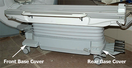
- Remove the front or rear base cover.
Figure 1. Front and Rear Base Covers
- notice
- Disengage the rear caster brake lock pedal.
- notice
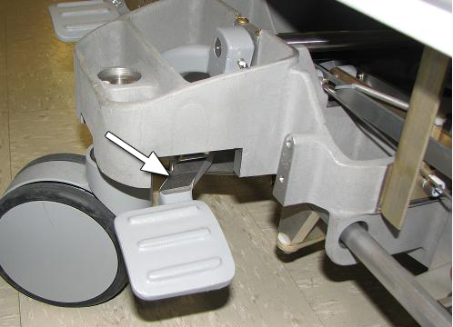
- At the caster to be replaced, use a 3/8 in. wrench to remove
the caster linkage pin.
Figure 2. Caster Linkage Pin, Collar and Bolt
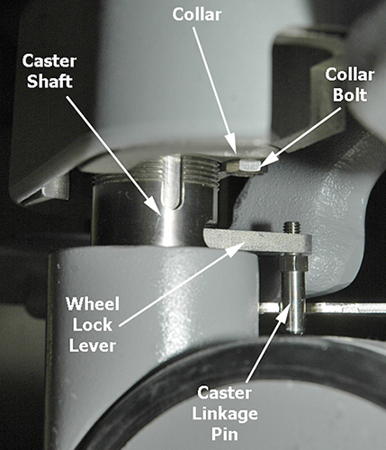 note:
note:Illustration depicts a floor-level view looking to the left from the right underside of the caster assembly. The orientation for each of the four casters is different so record the position of the collar and bolt hole while sliding the collar down the caster shaft.
- Remove the collar bolt (shown above) using a 7/16 in. wrench.
- Slide the collar down the shaft so it rests on top of the wheel lock lever.
- Looking from a top-down perspective, move the wheel lock lever
to the left.
Figure 3. Wheel Lever Lock Positions
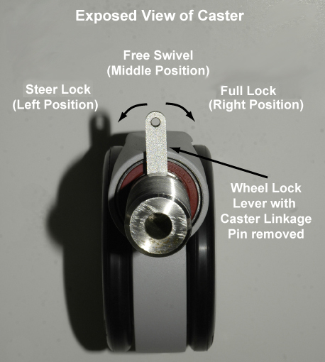
The wheel lock lever has three positions:
-
Full Lock or Brake is the right position that locks the caster so the patient table cannot move.
-
Free Swivel is the middle position that allows the caster to move freely.
-
Steer Lock is the left position that locks the caster in a direction, but the wheels can still spin.
-
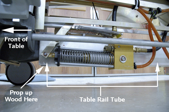
- Use a minimum 6.5 in. block of wood to prop up the bottom of
the patient table to raise it at least 2.5 in. off the floor (to establish
enough clearance to remove a caster), and turn the caster counterclockwise
until it releases from the caster assembly.
Figure 4. Positioning Block of Wood at Front of Table
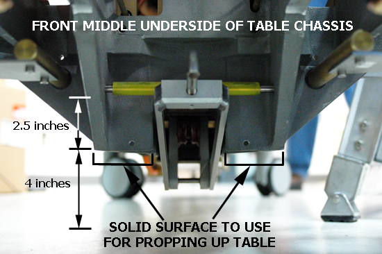
Figure 5. Positioning Block of Wood at Rear of Table
- notice
- Place a mark on the bottom of the collar for easy identification of placement, then remove the collar.
 |
|
|
Caster Replacement
Procedure
- Attach the collar to the new caster, reusing the caster linkage pin, collar, and collar bolt from the old caster. (Refer to your note regarding the correct orientation of the collar on the caster shaft.)
- notice
- Thread the new caster into the caster base by turning it clockwise.
- Return the table to all four casters on the floor, and measure the height of the new caster to achieve a measurement of 8.2 in. (207 mm). Refer to Leveling Patient Table. Use a nonferrous level to check the levelness of the patient table, and make the appropriate adjustments.
- Slide the collar up the caster shaft to its home position, wiggle the caster until the bolt holes line up, and rebolt the collar to the caster base.
- Apply Loctite 242 and replace the caster linkage pin on the new caster.
- Move the wheel lever lock to the free-swivel or middle position.
- Replace the caster base cover and patient table lower base cover.
- Dock the patient table and check the levelness.
|
Pedal Top Pad Replacement
Procedure
- Remove the lower side covers from the patient table.
- Remove the rear base cover shown in Figure 1.
- Remove the old rubber pad from the pedal, and clean the contact area with isopropyl alcohol.
- Position and install the new rubber pad as shown below. (The
replacement is a self-adhesive backed rubber piece.)
Figure 6. Pedal Top Rubber Pad
Wheel Replacement
Procedure
- Use a small flat-blade screwdriver to remove the wheel cover.
- Roll the wheel not being replaced over a piece of cardboard to raise the other wheel slightly.
- note:Use a snap ring pliers (1) to remove the snap ring (2) from the wheel.
The snap ring pliers can be found in the HEC cabinet.
Figure 7. Removing Wheel
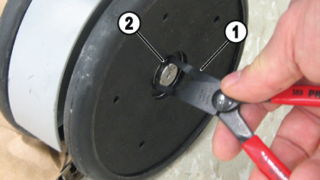
ITEM DESCRIPTION 1 Snap ring pliers 2 Snap ring - Remove wheel.
- Install new wheel.
 warning
- Install new snap ring. Make sure that the snap ring is properly seated in the groove.
- Install new cover.
- Repeat for other wheel.
 |
Finalization
Finalization
Ensure the caster brakes and steer lock work properly.