- id_12374844
- Version: 1.7
- Date: Feb 19, 2020 4:49:35 PM
Cradle Latch Replacement–Curved Table
Prerequisites
| Required persons | Preliminary requirements | Procedure | Finalization |
|---|---|---|---|
| 1 | Not Applicable | 45 minutes | 5 minutes |
| Item | Quantity | Effectivity | Part number | Manufacturer |
|---|---|---|---|---|
| Non-Ferrous Service Tool Kit | 1 | - |
5112581 |
- |
| Item | Quantity | Effectivity | Part number | Manufacturer |
|---|---|---|---|---|
| Cradle Latch Cable (cut to 1500 mm) | 1 | - |
Refer to FRU Manual |
- |
| Cradle Latch Housing | 1 | - |
Refer to FRU Manual |
- |
|
Overview
This procedure outlines the necessary steps for replacing the cradle latch housing for a 32-channel system or a 16-channel system. The 16-channel system does not allow for the complete removal of the cradle assembly.
Removing Cradle Latch Housing
Procedure
- Undock the patient table and move it out of the magnet room.
- Remove the upper bellows and left lower base side cover. See Patient Table Upper Bellows and Lower Base Side Cover Removal.
- Raise the table to its maximum height.
 warning
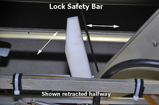
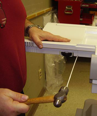
- Lower the table lock safety bar. Lower the table and verify
that all its weight is resting on the lock bar.
Figure 1. Table Lock Safety Bar
- Hold down the cradle latch block and press the cradle release
button at the same time.
Figure 2. Cradle Removal
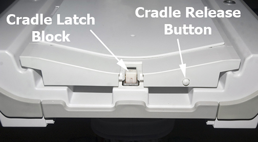
- While holding down the cradle latch block and pressing the cradle release button, slide the cradle forward enough so it covers the top area of the latch block. Let go of the cradle latch block and cradle release button.
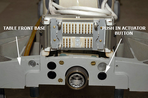
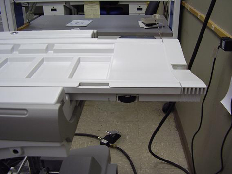
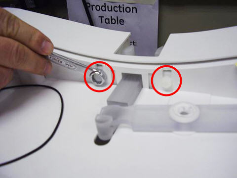
- Push in the right actuator on the table front base.
Figure 3. Table Front Base
- note:For a 16-channel system, prop up the cradle (see below) or remove it from the patient table to perform desired maintenance.
Pressing the actuator button engages the secondary cradle latch cable and causes the pin stop to move down flush with the table top surface, allowing the cradle to slide forward.
- For a 32-channel system, do one of the following:
- To remove the cradle from the table:
-
Use wood blocks (or similar) to prop up the rear of the cradle at least 12 inches above the table top to expose the cable take-up assembly.
-
Remove screws and cable cover.
note: These are specific, pure brass screws. Do not mix up or replace with standard brass screws. -
Remove the four screws.
-
Remove the two coil connector screws.
-
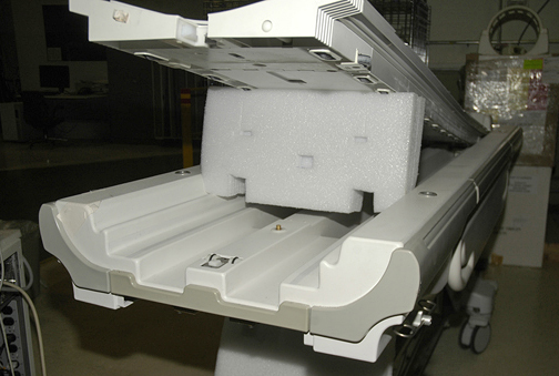
- To partially remove the cradle from the
table:
-
Slide the cradle forward far enough to clear the cradle guide rail latches at the rear of the table.
-
Use wood blocks (or similar) to prop up the front of the cradle.
-
Figure 4. Propping Up Back of Cradle
- To remove the cradle from the table:
- With the cradle raised, remove the cable covers at the head
of the cradle, held by two screws on each side.
Figure 5. Cable Cover Removal
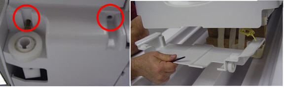
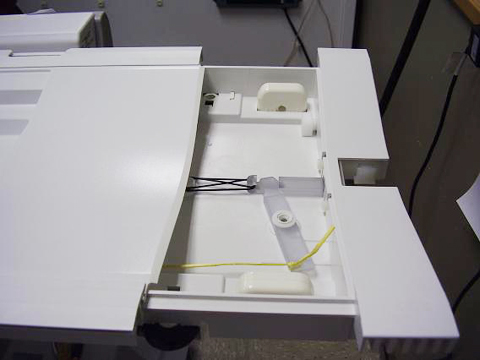
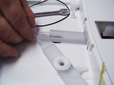
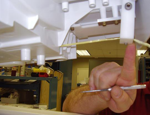
- Untie the knot in the Kevlar cord. A scribe or other tool may
be needed to loosen the knot.
Figure 6. Kevlar Cord Knot and Release Lever Screw
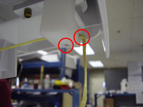
- Remove the screw on the bottom of the release lever that holds the Kevlar cord in place.
- Pull out the rivet from the side of the release lever, noting
that the Kevlar cord is positioned over the rivet.
Figure 7. Release Lever Rivet
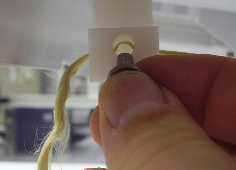
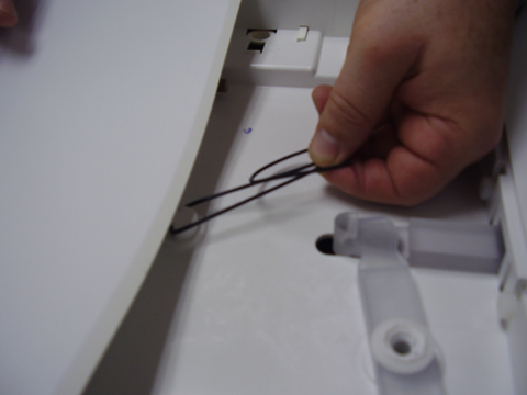
- Pull the Kevlar cord through the release lever approximately
6 inches. DO NOT pull the cord out of the release
lever completely.
Figure 8. Loosen Kevlar Cord
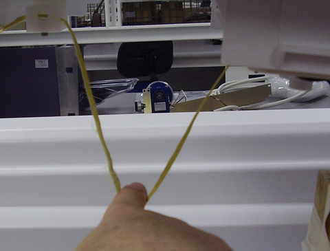
- Remove the blocks or other structure used to elevate the cradle.
Put the cradle back down so that there is approximately 18 in (46
cm) overhang at the foot of the table.
Figure 9. Cradle Position
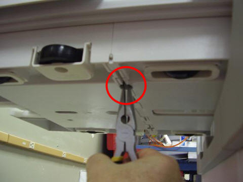
- Pull the cradle hinge pin out. The cradle hinge pin can only
be removed on the left side of the table. Push out the pin on the
side using large needle nose pliers.
Figure 10. Remove Hinge Pin
- After the hinge pin is removed, slide the front cradle section
out.
Figure 11. Extend Cradle Section
- Remove the rubber latch spring.
Figure 12. Remove Latch Spring
- Remove the two nylon screws.
Figure 13. Remove Nylon Screws
- Unhook the release lever from the release bar. This is accomplished
by pulling the release bar, lifting slightly, and away from the lever.
The latch assembly will then be free to pull down and remove.
Figure 14. Remove Release Lever
- note:Remove the cradle latch assembly from table cradle.
There are two Delrin springs installed on each side of the latch assembly. Keep these springs for reuse with the new cradle latch assembly.
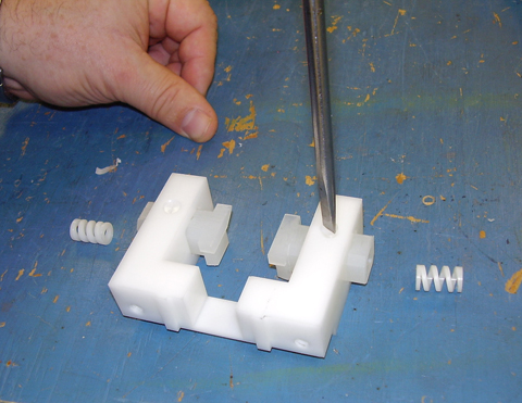
- Remove the two plastic screws on top of the removed latch assembly.
Then remove the latch blocks. Note the orientation of the angles on
the latch blocks for installing the new cradle latch assembly.
Figure 15. Cradle Latch Disassembly
Installing Cradle Latch Assembly
Procedure
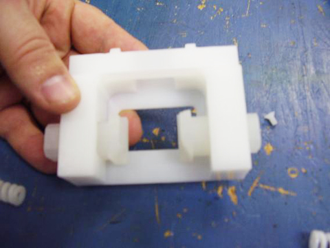
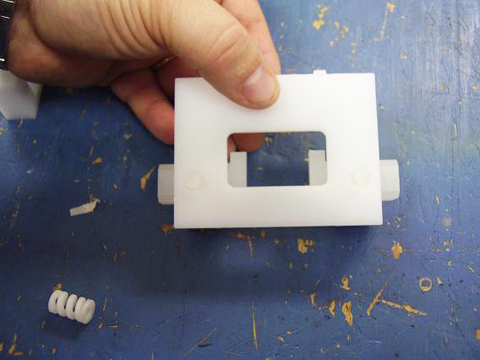
- Install latch blocks and plastic screws into the new latch assembly.
Make sure the screws go through the slots on the latch blocks. When
assembled properly, the latch blocks will have limited side-to-side
movement but will not fall out of the assembly.
Figure 16. New Cradle Latch Assembly
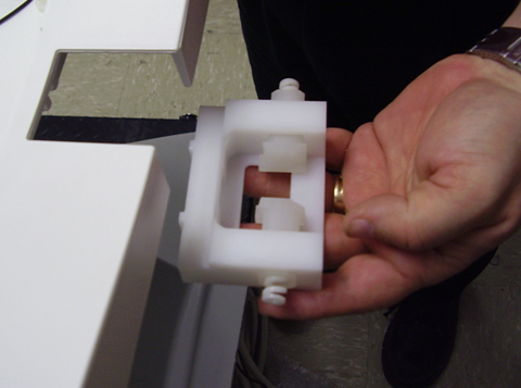
- After the new cradle latch assembly is assembled, position the
flat side of the latch blocks on the bottom.
Figure 17. Latch Block Orientation
- Install the new cradle latch assembly into the table.
Figure 18. Latch Installation
- Install nylon screws. See Figure 13.
- Install the new release bar with the new latch assembly. This requires lifting the end of the release lever to place the release bar into the guide slot as performed in Step 20.
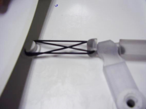
- Replace the rubber latch spring.
Figure 19. Reinstall Latch Spring
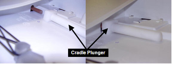
- Position the front cradle plunger onto the cradle rod.
Figure 20. Cradle Rod Re-Installation
- Slide the cradle back together. Install the hinge rod. A hammer
may be required to tap the hinge rod back into position.
Figure 21. Hinge Pin Installation
- Lift the cradle and support it to gain access to the Kevlar cord. See Figure 4.
- Insert the rivet back into the release lever, ensuring that
the Kevlar cord is routed OVER the rivet when
it is installed as shown in Figure 7. Pull the Kevlar cord taut without causing the
release bar to protrude into the latch housing. The lever should be
pushed toward the front of the cradle when performing this step.
Figure 22. Release Bar Lever
- Verify that the release mechanism is not pulled out, then tighten the screw in the release lever.
- Tie a new knot in the Kevlar cord running through the release lever. See Figure 6.
- Raise the table lock safety bar.
- Install the covers. See Step 10.
- Perform Cradle/Table Release Block Adjustment.
Finalization
Finalization
Verify that the cradle attaches to the LPCA, and the latch mechanism operates properly.