- id_12373798
- Version: 1.8
- Date: Feb 19, 2020 1:10:18 PM
Patient Table Up Limit Replacements
Prerequisites
| Required persons | Preliminary requirements | Procedure | Finalization |
|---|---|---|---|
| 1 | Not Applicable | 30-120 minutes | 15-30 minutes |
| Item | Quantity | Effectivity | Part number | Manufacturer |
|---|---|---|---|---|
| 5/16 hex bit (3/8 drive) | 1 | - | - | - |
| Non-ferrous Tool Kit | 1 | - |
5112581 |
- |
| Torque Wrench | 1 | - |
5534134 |
- |
| Item | Quantity | Effectivity | Part number | Manufacturer |
|---|---|---|---|---|
| Loctite 242 | As needed | - |
See FRU Manual |
- |
| Item | Quantity | Effectivity | Part number | Manufacturer |
|---|---|---|---|---|
| Up Sensor Cable | 1 | - |
See FRU Manual |
- |
| Up Sensor Cable Tubing | 1 | - |
See FRU Manual |
- |
| Up Sensor Top Bracket | 1 | - |
See FRU Manual |
- |
| Up Sensor Cable | 1 | Curved table |
See FRU Manual |
- |
| Up Sensor Cable Tubing | 1 | Curved table |
See FRU Manual |
- |
| Up Sensor Top Bracket | 1 | Curved table |
See FRU Manual |
- |
Overview
The patient table up limit switch components are used to set the hydraulic cylinder upper limit. This procedure explains how to replace the patient table up limit switch components.
There are two possible configurations for the table up limit – cable or hook (switch). Follow the instructions for the type of table you are servicing.
The up limit switch mounting bracket for an electrical table requires two persons and the timing varies depending on whether the cradle is removed or not.
See each procedure for specific timing and number of required persons.
Up Sensor Cable and Tubing Replacement (Curved Table Only)
Required Persons: 1. Procedure Timing: 30 minutes.
Procedure
- Undock the patient table and remove it from the magnet room.
- Remove the right upper bellows and right lower base side cover, and the front base cover. See Patient Table Upper Bellows and Lower Base Side Cover Removal.
- Raise the table to its maximum height.
 warning
- Lower the table lock safety bar.
Figure 1. Table Lock Safety Bar
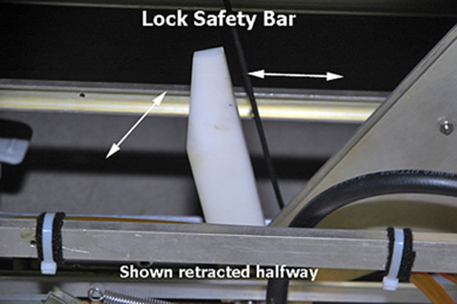
- Lower the table and verify that all of the table top's weight is resting on the safety bar.
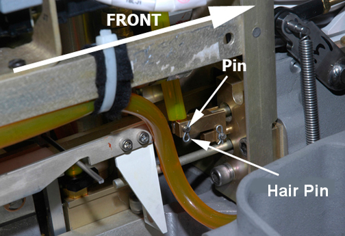
- Remove the hair pin and retaining pin securing the bottom end
of the cable to the bell crank.
Figure 2. Pin and Hair Pin
- If you are only replacing the up sensor cable tubing, follow these steps:
- Remove the clamp securing the cable to the up sensor top bracket.
Figure 3. Table Up Limit Cable Replacement
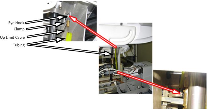
- Remove the retaining ring and washer securing the end of the cable to the up limit pin on the bracket.
- Install the new up sensor cable and attach it to the up limit pin.
- Fasten the other end of the cable to the bell crank and secure the retaining pin with the hair pin. (See Figure 2)
- Attach the clamp securing the cable to the bracket.
- Adjust the table up limit cable length to provide enough slack so that when the cylinder is fully raised in the next step, the cable is not stretched and damaged.
- Fully raise the cylinder.
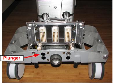
- Adjust the table up limit cable so that the plunger can move
1 to 2 mm when the hydraulic cylinder is fully extended.
If the cable is too loose, the plunger will not engage the dock switch fully and the system will not recognize that the table is fully up.
If the cable is too tight, the cable may break.
Figure 4. Table Dock Push Button
- If there are no additional replacements, proceed to Finalization. Otherwise, continue with the appropriate section below.
Up Sensor Top Bracket Replacement (Curved Table Only)
Required Persons: 2. Procedure Timing: 90 minutes.
Procedure
- Undock the patient table and remove it from the magnet room.
- Remove the right upper bellows and right lower base side cover, and the front base cover. See Patient Table Upper Bellows and Lower Base Side Cover Removal.
- Raise the table to its maximum height.
- warning
- Lower the table lock safety bar.
Figure 5. Table Lock Safety Bar
- Lower the table and verify that all of the table top's weight is resting on the safety bar.
- Release the cradle and manually slide the cradle forward and either:
-
Have another person hold the cradle end up so you have access to the table top height adjustment screw.
or
-
Remove the cradle completely.
-
- Use a flat head screwdriver to remove the cover plug from the table top height adjustment screw.
- Use needle-nose pliers to remove the e-clip from the end of
the table top height adjustment screw.note:
Place a piece of tape over part of the e-clip before removing it so that the e-clip does not become lost during removal. Remove the tape after removing the e-clip.
- If the cradle was not removed, slide the cradle back onto the table.
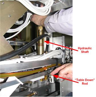
- While moving the table down rod to the rear of the table, pull
down on the hydraulic shaft. Stop when the hydraulic shaft is low
enough to access the top of the up sensor top bracket.
Figure 6. Hydraulic Shaft
- Remove the two screws (at the top of the hydraulic cylinder)
attaching the up sensor top bracket to the hydraulic cylinder. Replace
the up sensor top bracket.note:
The top can be rotated, which also changes the table height. Make sure to return the top back to its original position.
- Carefully raise the table. The hydraulic cylinder must fit through the hole in the table. Check that the hydraulic cylinder is completely within the hole and that the table height adjustment is accessible.
- If the cradle is still attached to the table, release the cradle, manually slide the cradle forward, and have another person hold the end of the cradle so you have access to the table top height adjustment screw.
- Re-attach the e-clip and cover plug.
- If the cradle was not removed, slide the cradle back onto the table. Otherwise, reinstall the cradle.
- Fully raise the cylinder.
- Adjust the table up limit cable so that the plunger can move
1 to 2 mm when the hydraulic cylinder is fully extended. See Figure 4.
If the cable is too loose, the plunger will not engage the dock switch fully and the system will not recognize that the table is fully up.
If the cable is too tight, the cable may break.
- If there are no additional replacements, proceed to Finalization. Otherwise, continue with the appropriate section below.
Finalization
Procedure
- Verify proper operation of the table.
- Raise the table lock safety bar.
- Dock the table.
- Verify proper up/down table motion.
- When the table is in a fully raised position, verify that the cradle and LPCA can be advanced normally into the bore.
- Verify that raising the table to its full height results in the LPCA automatically driving out to engage the cradle.
- Verify that lowering the table results in automatic retraction of the LPCA into the bridge.
- Verify normal cradle and LPCA motion from the home position to end of travel on the bridge using enclosure In Fast and Out Fast buttons at the operator console.
- Replace the upper bellows and lower base covers, and the front base cover.