- id_12374877
- Version: 1.5
- Date: Feb 19, 2020 4:48:08 PM
Cradle Latch Block Replacement
Prerequisites
| Required persons | Preliminary requirements | Procedure | Finalization |
|---|---|---|---|
| 1 | Not Applicable | 50 minutes | 5 minutes |
| Item | Quantity | Effectivity | Part number | Manufacturer |
|---|---|---|---|---|
| Non-Ferrous Service Tool Kit | 1 | - |
5112581 |
- |
| Item | Quantity | Effectivity | Part number | Manufacturer |
|---|---|---|---|---|
| Loctite 242 | 0.5 CC | - |
46-170686P1 |
- |
| Item | Quantity | Effectivity | Part number | Manufacturer |
|---|---|---|---|---|
| Cradle Latch Cable (cut to 1500 mm) | 1 | - |
Refer to FRU Manual |
- |
| Cradle Latch Housing | 1 | - |
Refer to FRU Manual |
- |
|
Overview
This procedure outlines the necessary steps for replacing the cradle latch housing for a 32-channel system. It applies to all DV tables.
Procedure
- Undock the patient table and move it out of the magnet room.
- Remove the upper bellows and left lower base side cover. See Patient Table Upper Bellows and Lower Base Side Cover Removal.
- Raise the table to its maximum height.
 warning
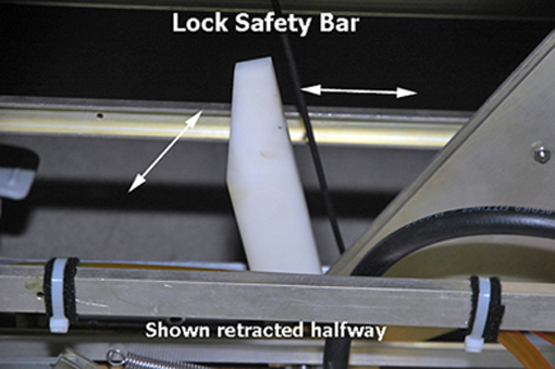
- Lower the table lock safety bar. Lower the table and verify
that all its weight is resting on the lock bar.
Figure 1. Table Lock Safety Bar
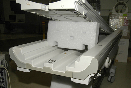
- Manually slide the cradle forward and prop it up. See Removing Cradle Assembly.
Figure 2. Propping Up Cradle
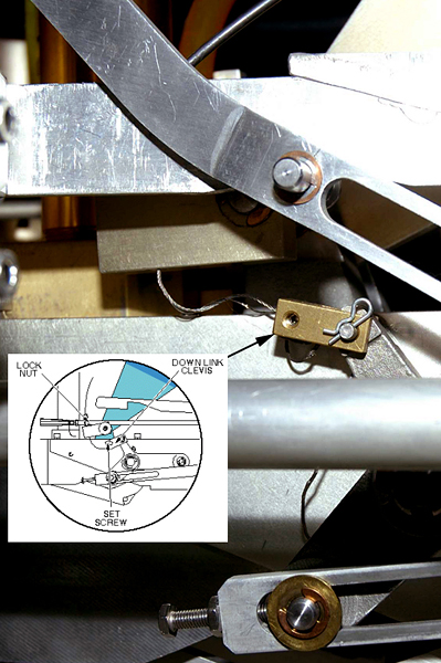
- Using a 5/64 Allen wrench, loosen the set screw at the down
link clevis.
Figure 3. Down Link Clevis
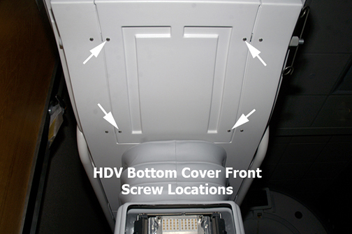
- Remove the patient table bottom front cover.
Figure 4. Patient Table Bottom Front Cover
- caution
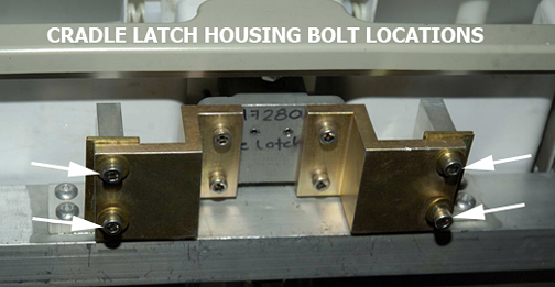
- Remove four bolts securing the cradle latch housing and the
cradle latch cover.
Figure 5. Cradle Latch Housing Bolts
- Unfasten the cable end from the down link clevis (see Figure 3).
- Pull the cable out of the cradle latch block on the front of
the patient table.
Figure 6. Interlock Cable and Main Cradle Latch Cable Routing
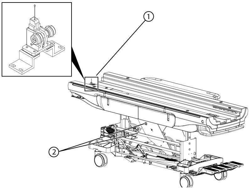
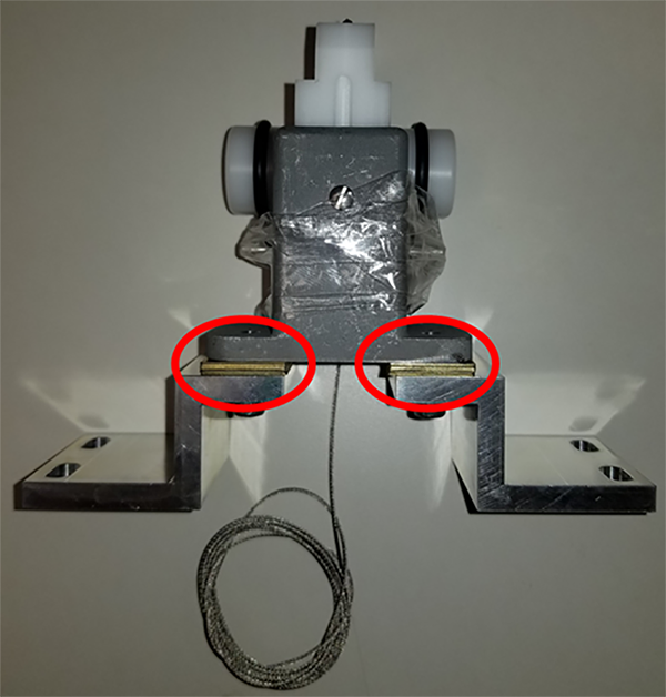
1 Front latch assembly 2 Cable fastener location - Add or remove brass shims on the replacement assembly to match the number of shims from the original assembly.
Figure 7. Cradle latch assembly shims
- Remove the limit screw at the back of the cradle latch housing. Extract the plastic latching mechanism and replace.
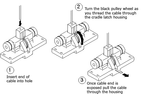
- Insert the new cable through the head of the cradle latch block
so after it is fully threaded, the swaged end fits into the hole in
the latch pin.
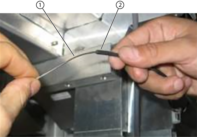
Figure 8. Installing Main Cradle Latch Cable
- Insert the cable into the sheath and feed the entire cable through the sheath.
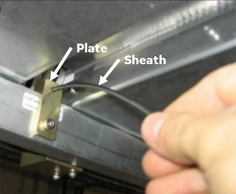
Figure 9. Cradle latch cable sheath
1 Cable 2 Sheath - Slide the sheath along the cable into the plate, towards the front latch.
Figure 10. Feeding the sheath into the plate
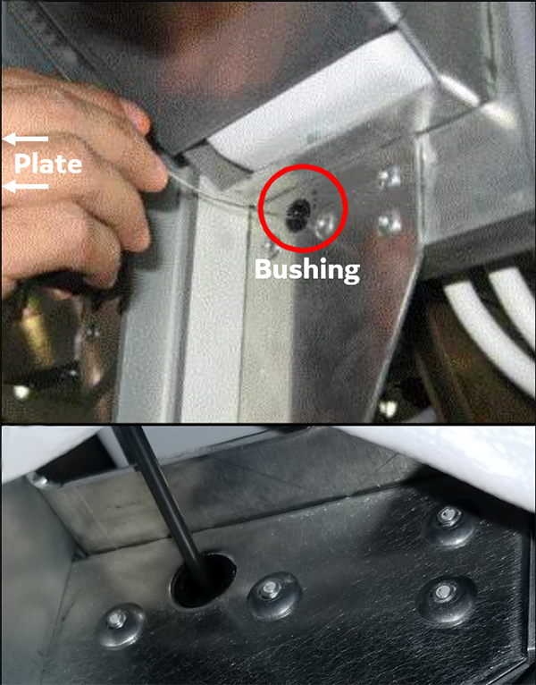
- Feed the cable and the sheath through the bushing located opposite of the plate.
Figure 11. Cable and sheath bushing
- Reinstall the cradle latch housing.
- Before continuing, move the fine adjust screw all the way in (tight to the block).
- Rotate the three-legged casting by hand (or have a second person
press the table pedal), and put a tool such as an Allen wrench in
the mechanism to hold the table in the docked position.
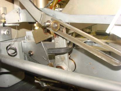
Figure 12. Tool Holding Table in Docked Position
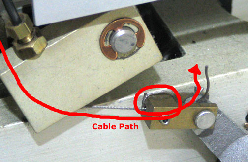
- Route the cable through the cable casing and insert the cable through the down link clevis (see Figure 3).
- Loop the cable twice through the hole in the down link clevis.
Figure 13. Cable Path through Down Link Clevis
- Pull the cable taut. Pull until the main latch is as low as it can go.
- Put Loctite on the set screw.
- Tighten the set screw (see Figure 3).
- Remove the tool used in Step 19.
- Use the pedal to cycle the cable movement 10 times.
- Use the fine adjust screw to readjust as needed.
- Return to the magnet room and dock the patient table.
- Adjust the cable so that when the table is docked, the main latch is flush with the casting. For details, see Cradle Release Block Adjustment.
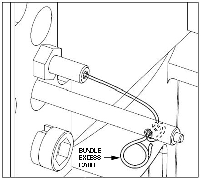
- Loop the excess cable multiple times to bundle it.
Figure 14. Bundling Excess Cabling
- Re-dock the patient table.
 |
Finalization
- Raise the table lock safety bar.
-
Verify proper operation of the latching interlock.
-
Replace the cradle, and the upper bellows and lower base side cover.