- id_13107113
- Version: 2.9
- Date: Dec 18, 2019 6:50:06 PM
Patient Table Braking System Replacements
Prerequisites
| Required persons | Preliminary requirements | Procedure | Finalization |
|---|---|---|---|
| 1 | Not Applicable | 30-60 minutes | 5 minutes |
| Item | Quantity | Effectivity | Part number | Manufacturer |
|---|---|---|---|---|
| Non-Magnetic Tool Kit | 1 | - |
5113258 or 5112581 |
- |
| Item | Quantity | Effectivity | Part number | Manufacturer |
|---|---|---|---|---|
| Cable Ties | As needed. | - | - | - |
| Loctite 242 | 0.5 CC | - |
46-170686P1 |
- |
| Item | Quantity | Effectivity | Part number | Manufacturer |
|---|---|---|---|---|
| Shoulder Screw, IN ¼-20 x 3/8, SS18-8 | 3 | - |
See itemized Table parts list in FRU Manual. |
- |
| Shoulder Screw, IN ¼-20 x 5/8, SS18-8 | 2 | - |
See itemized Table parts list in FRU Manual. |
- |
| Nylon Washer | 9 | - |
See itemized Table parts list in FRU Manual. |
- |
| Rubber Washer | 1 | - |
See itemized Table parts list in FRU Manual. |
- |
| Shaft Linkage-Right | 1 | - |
See itemized Table parts list in FRU Manual. |
- |
| Shaft Linkage-Left | 1 | - |
See itemized Table parts list in FRU Manual. |
- |
| Link - Reversing | 1 | - |
See itemized Table parts list in FRU Manual. |
- |
| Link - Left Rear | 1 | - |
See itemized Table parts list in FRU Manual. |
- |
| Link - Left Front | 1 | - |
See itemized Table parts list in FRU Manual. |
- |
| Link - Right Rear | 1 | - |
See itemized Table parts list in FRU Manual. |
- |
| Link - Right Front | 1 | - |
See itemized Table parts list in FRU Manual. |
- |
| Bearing IGUS MCI-12-02 | 4 | - |
See itemized Table parts list in FRU Manual. |
- |
| Shaft Extension | 2 | - |
See itemized Table parts list in FRU Manual. |
- |
| Mounting Block | 1 | - |
See itemized Table parts list in FRU Manual. |
- |
| Pin - Actuator | 4 | - |
See itemized Table parts list in FRU Manual. |
- |
|


This procedure explains how to replace various components in the Table braking system and various braking system checks at the completion of the replacements. The replacements and functions covered in this document include:
Shaft Linkage-Right, Shaft Extension, and Bearing IGUS Replacement
Caster Pin Actuator Replacement
Left rear brake link replacement
Right rear brake link plate replacement
Front left and right brake link plate replacement
Step 3 (Braking system checks)
Shaft Linkage-Right, Shaft Extension, and Bearing IGUS Replacement
This procedure is written for the right side of the Table. The procedure for the left side of the Table, as seen in Figure 1, is similar.
Shaft Linkage-Right, Shaft Extension, and Bearing IGUS Removal
Procedure
- Undock the Table and remove it from the magnet room.
Figure 1. Table Covers
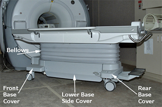
- Remove both Lower Base Side Covers by removing the two screws that fasten each Cover to the Table assembly. Lift up and pull out the Covers. Note that Velcro strips attach the Lower Base Side Covers to the Bellows. See Patient Table Upper and Lower Base Side Cover Removal for more information.
- Remove Front and Rear Base Covers by removing the two front
screws and the two screws that attach the Bellows.
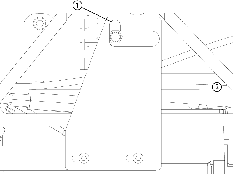
Figure 2. Rear Base Cover
- Raise the Table to its maximum height.
- Lower the Table’s Lock Safety Bar. Lower the Table to
ensure all weight is resting on the lock bar.
Figure 3. Table Lock Safety Bar
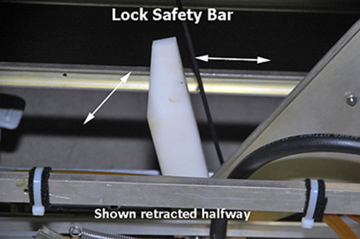
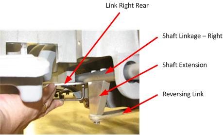
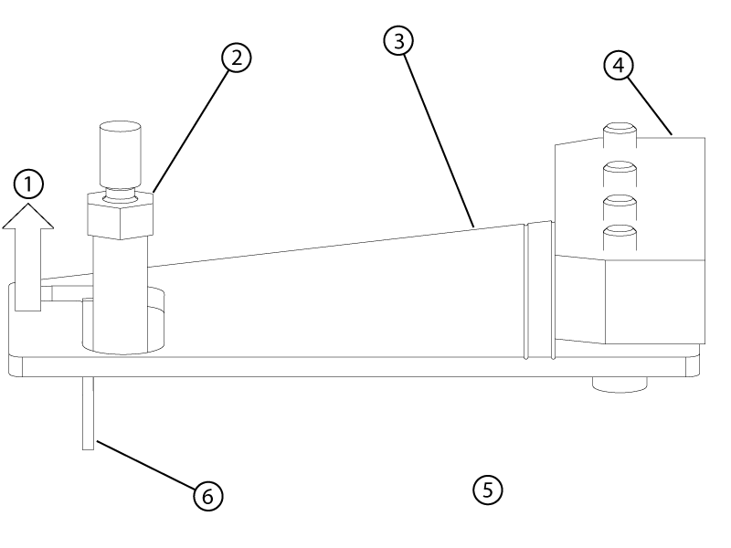
Figure 4. Isometric Assembly
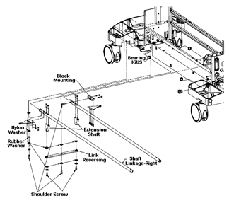
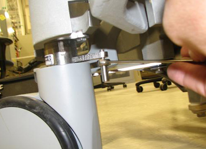
- Remove the screws that attach the Shaft Linkage-Right to the
Link-Right Rear, located at the right rear side of the Table. Also
remove the two screws that attach the Link-Right Front on the opposite
side of the Table in the same location.
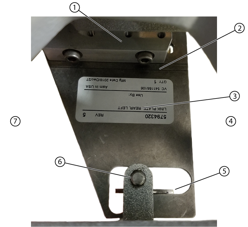
Figure 5. Shaft Linkage, Right Rear
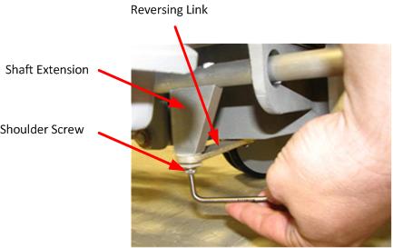
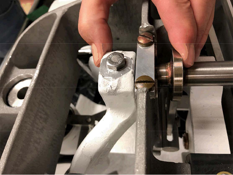
- Remove the Shaft Extension from the Shaft Linkage Right.
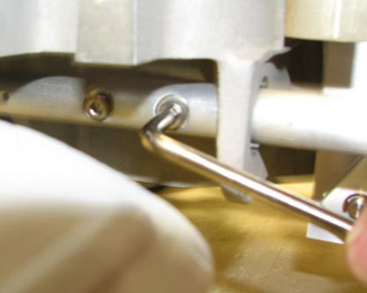
- Remove the shoulder screw, as shown below.
Figure 6. Removing the Shoulder Screw
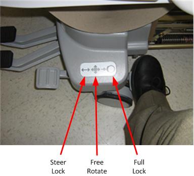
- For best access to Shaft Extension mounting screws, put the
Table brake in "free rotate" position.
Figure 7. Brake Positions
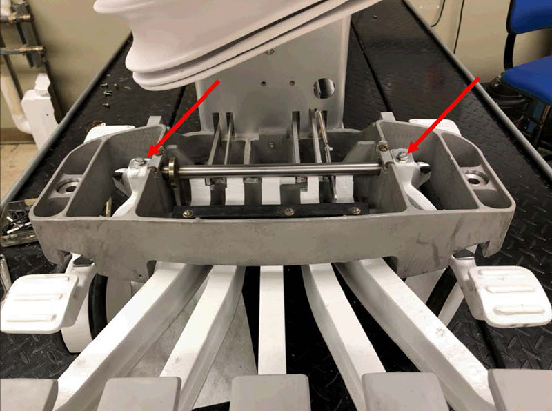
- Remove the Shaft Extension mounting screws. (If more space is
needed to access the Shaft Extension mounting screws or for better
torque, rotate the bottom of the Shaft Extension out.)
Figure 8. Shaft Extension Mounting Screws
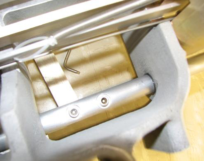
Figure 9. Removing Shaft Extension Screws
- Remove the shoulder screw, as shown below.
- If replacing the Shaft Extension, install the new Shaft Extension. Apply Loctite when reinstalling the mounting screws. Otherwise, continue on to the next step.
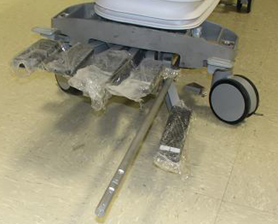
- Press the lower pedal to create space to remove the Shaft Linkage
through the rear of the Table.
Figure 10. Removing the Shaft Linkage
- If replacing front or rear bearing IGUS, remove the bearing
IGUS by hand and replace as required.
Figure 11. Bearing IGUS
Shaft Linkage-Right and Shaft Extension Installation
Procedure
- Press the lower pedal to create space and replace the Shaft Linkage through the rear of the Table.
- Replace the Shaft Extension in the Shaft Linkage Right.
- For best access to Shaft Extension mounting screws, put the Table brake in "free rotate" position.
- Replace the Shaft Extension mounting screws. (If more space is needed to access the Shaft Extension mounting screws or for better torque, rotate the bottom of the Shaft Extension out.) Apply Loctite when reinstalling the mounting screws.
- Replace the shoulder screw.
- Replace the screws that attach the Shaft Linkage-Right to the Link-Right Rear, located at the right rear side of the Table. Also replace the two screws that attach the Link-Right Front on the opposite side of the Table in the same location.
- Raise the Table and raise the Lock Safety Bar for normal operation.
- Replace both the Front and Rear Base Covers. Reinstall the two front screws and the two screws that attach the Bellows.
- Replace both Lower Base Side Covers. Reinstall the two screws that fasten each Cover to the Table assembly. Note that Velcro strips attach the Lower Base Side Covers to the Bellows.
Reversing Link Replacement
Procedure
- Undock the Table and remove it from the magnet room.
- See Figure 4 and Figure 6 for the location of the shoulder screws. Shoulder screws are accessible
from the bottom of the Table.note:
There are plastic washers on both sides of the mounting holes. Take care to prevent damaging the washers during the replacement procedure. Also, both outer shoulder screws have brass washers installed. See Figure 6.
- Replace the Reversing Link bar and shoulder screws as required. Tighten the shoulder screws. The shoulder screw will allow some movement of the reversing bar when installed.
Mounting Block Replacement
Procedure
- Undock the Table and remove it from the magnet room.
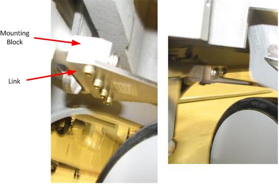
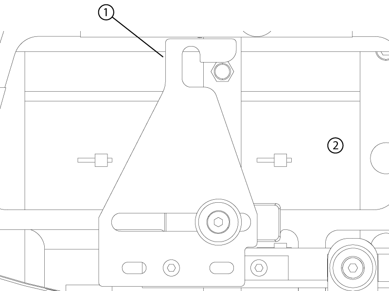
- See Figure 4 and Figure 5. The block assembly is attached to the Shaft Linkage-Left using
two screws and the Link-Left Rear with four bolts. Remove the bolts
as required. See the illustration below.
Figure 12. Left Rear Link and Mounting Block
- (For Systems with old-style link plates) , replace the Shaft Linkage-Left using two screws and the Link-Left Rear with four bolts. Apply Loctite when reinstalling the bolts.
- (For System with new-style link plates) , replace the shaft-linkage left using two screws and see Left rear brake link replacement to reinstall the left rear brake link.
Caster Pin Actuator Replacement
The pin actuator is a threaded pin that bolts into the caster arm.
Procedure
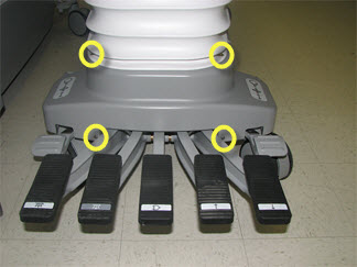
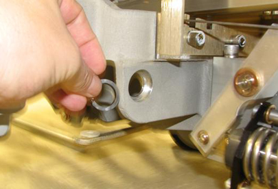
- Loosen and remove the caster pin actuator. See the following
illustration.
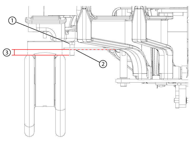
Figure 13. Caster Pin Actuator
- Replace the caster pin actuator. Apply Loctite when reinstalling.
Left rear brake link replacement
Procedure
- Loosen the bolts securing the brake pedals to the cross bar of the pedal rod assembly.
Figure 14. Pedal rod bolts
- Squeeze the left pedal and brake plate extension tight against the table frame.
Figure 15. Pedal rod adjustment
- Tighten the left-side bolt to secure the pedal to the pedal rod.
- Push the right brake pedal to the table frame to eliminate any gap.
- Tighten the right-side bolt to secure the pedal to the pedal rod.
- Remove the four screws and four washesrs securing the left rear brake link plate to the mounting block.note: Discard the four removed screws.
Figure 16. Left rear brake link plate mounting
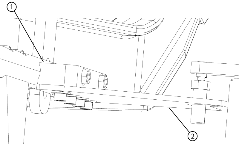
1 Mounting block 2 Link - Apply Loctite to the four new screws.
- Install the new link plate and loosely install the four new screws and four new washers.note: Allow play in the link plate for fine adjustments in the following steps.
- Align the brake link plate as follows:
Figure 17. Left rear link alignment (view from the top)
1 Mounting block 2 Scribe line 3 Link plate 4 Handle side 5 Shim 6 Caster pin 7 Dock side - Push the brake link plate towards the rear (handle end) of the table until it stops.
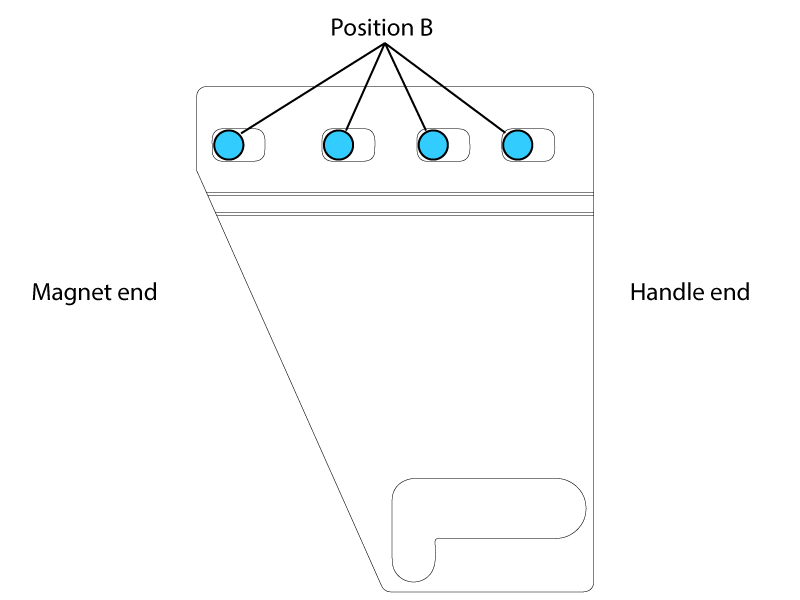
Figure 18. Slot position B
- Lift up on the end of the brake linkage plate until it is horizontal to the ground. Continue holding everything in position until the screws are tightened.
Figure 19. Left rear link alignment isometric view
1 Lift up 2 Caster pin 3 Left rear link 4 Mounting block 5 Handle end of the table 6 Shim - Make sure the caster pin is in the neutral position.
- Make sure that the brake link plate and the caster pin are 2mm apart using shim (5814640).
- Make sure that the scribe line on the brake link plate is parallel with the mounting block edge.
- Push the brake link plate towards the rear (handle end) of the table until it stops.
- Tighten the four screws securing the plate to the mounting block.
- Make sure the link plate and the caster pin are still 2mm apart using the shim and that the link plate is rigid.
Right rear brake link plate replacement
Procedure
- Make sure the caster pin is in its neutral position.
- Remove the old right rear link by removing the two screws securing the plate to the right shaft linkage. Remove the shoulder screw containing the nylon hardware.
- Install the right rear link plate with the open side of the caster pin hook towards the front of the table.
Figure 20. Right rear brake link plate (view from the top)
1 Caster pin hook 2 Front of table - Apply Loctite and install the shoulder screw by hand in the assembly order shown below.note: Forward to rear positioning of the linkage with respect to the screw is not important.
Figure 21. Shoulder screw stackup
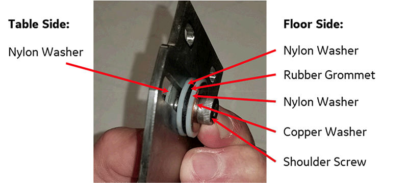
- Apply Loctite and install the two new screws and tighten to secure in place.
- Tighten the shoulder screw.
- Apply Loctite and install the shoulder screw by hand in the assembly order shown below.
Front left and right brake link plate replacement
Procedure
- Make sure the caster pin is in its neutral position.
- Remove the front plate link by removing the two screws securing it to the shaft linkage.
Figure 22. Front right (closed travel path) brake link plate (view from bottom)
1 Caster pin hook 2 Front of table - Apply loctite to two screws.
- Loosely install the right front plate link with the hook side of the caster pin hook towards the front of the table.note: Forward to rear positioning of the linkage with respect to the screw is not important.
Finalization
Procedure
- Make sure the nut portion of the caster pin is above the hook of the brake linkage plate. Adjust the caster to bring the nut above the hook if required.
- For all replaced parts, make sure there is sufficient contact area where the caster pin and the brake linkage plate hook engage. Adjust the caster to create contact area if required.
Figure 23. Caster pin engagement
1 Caster pin nut above the link plate 2 The plate may sag. Lightly push the plate down to lowest sag point. 3 Minimum of 2mm below the plate at its lowest point - Raise the table and then raise the Table Lock Safety Bar for normal operation.
- Apply the wheel brake in the “full lock” position as shown in Figure 7.
- Make sure that each wheel is locked by trying to rotate the table left and right from each end.No wheel should roll.note: Slight wheel caster from side-to-side on the rear wheels is allowed.
- Put the wheel brake in the "free rotate" position. Rotate the table left and right. Confirm that each wheel casters and rolls.
- Put the wheel brake in the "steer lock" position. Rotate the table left and right. Confirm that both the rear the right front wheels caster.The left front wheel should remain oriented longitudinally along the table (It could rotate up to 180 degrees before locking).
- If a caster fails the finalization test, consider adjusting that associated link from its current position to the opposite position (position A to position B or position B to position A).
Figure 24. Left rear brake link plate (view from top)
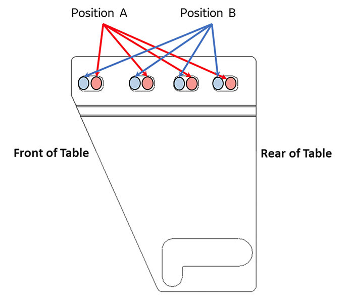
Figure 25. Right rear brake link plate (view from top)
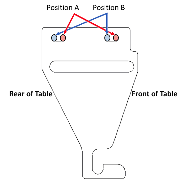
Figure 26. Right front brake link pate (closed travel path) (view from top)

- Repeat Step 3 through Step 6 if any adjustments are made.
- Verify proper operation of the Table.
- Dock the Table.
- Verify proper up/down Table motion.
- When Table is in fully raised position, verify that the Table is level with the Bridge.
- Verify that raising Table to full height results in LPCA automatically driving out to engage Cradle.
- When Table is in fully raised position, verify that Cradle and LPCA can be advanced normally into bore.
- Verify that lowering the Table results in automatic retraction of LPCA into Bridge.
- Verify normal Cradle and LPCA motion from “home” position to end of travel on Bridge using enclosure In Fast and Out Fast buttons at the Operator's Console.