- id_12374694
- Version: 1.7
- Date: Jan 24, 2020 12:23:28 PM
Table/dock connector and Touch-n-Go (TnG) cable replacement
Prerequisites
| Required persons | Preliminary requirements | Procedure | Finalization |
|---|---|---|---|
| 2 | Not Applicable | 90 minutes | Not Applicable |
| Item | Quantity | Effectivity | Part number | Manufacturer |
|---|---|---|---|---|
| Cable Ties | As needed | - | - | - |
| Flat-Blade Screwdrivers, small and medium | 1 each | - | - | - |
| 3.0T MCRv Tool | 1 | - |
5182417-2 |
- |
| 1.5T MCRv Tool | 1 | - |
5182417 |
- |
| Nonmagnetic Tool Kit | 1 | - |
5112581 |
- |
| Item | Quantity | Effectivity | Part number | Manufacturer |
|---|---|---|---|---|
| Loctite® 242 Threadlocker (medium strength, 0.5 cc tube) | 1 tube | - |
See FRU manual. |
- |
| Item | Quantity | Effectivity | Part number | Manufacturer |
|---|---|---|---|---|
| Self-Locking Cable Tie | 5 | - |
46-208758P5 |
- |
| Table Side Dock Connector (includes table cable & ODU harness) | 1 | - |
See FRU manual. |
- |
| Dock Side Dock Connector (includes cable & ODU harness to reroute box) | 1 | - |
See FRU manual. |
- |
| Bumper Touch and Go Cable Assembly | 1 | - |
See FRU manual. |
- |
|


Overview
The patient table and dock each contain a connector plate that passes data from the table to the Reroute Box, then to the RF Hub. The patient table houses two port connectors (P3 and P4) at the rear of the cradle. Signals flow from the patient table to the system by way of several cables with connecting points. When the patient table and dock are connected, data travels between two types of connectors, coax for RF signal and pin/socket for control. The most important connection is where the patient table connects to the magnet via the dock. This document describes replacing each side of this connection.
Table connector
Table connector plate removal
Procedure
- Undock the Patient Table and remove it from the Magnet Room.
- Fasten the Upper Base Cover in the up position, and remove the Lower Base Cover. Refer to Patient Table Upper and Lower Base Cover Removal.
- Remove the Front Base Cover.
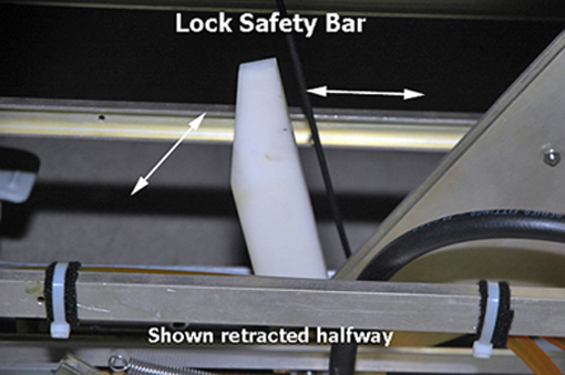
- Lower the table Lock Safety Bar (shown below), lower the table,
and ensure weight is resting on the lock bar.
Figure 1. Table lock safety bar
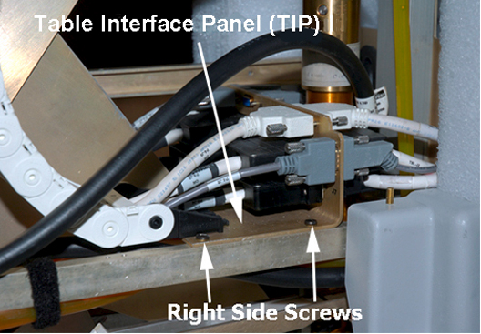
- Remove the two screws on each side of the Table Interface Panel
(TIP). This allows movement of the panel back allowing access to the
cable connector screws.
Figure 2. Table interface panel screws
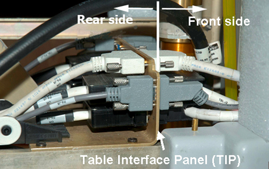
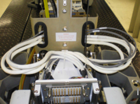
- Remove all cable connections from the front side of the TIP
shown below.
Figure 3. Front side cable connections
- notice
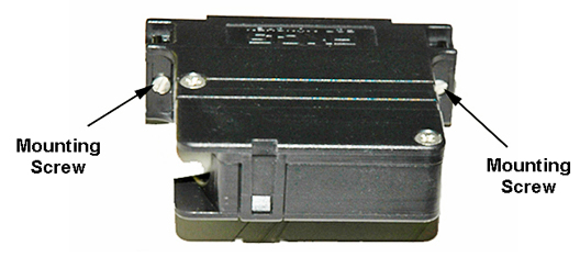
- Use small and medium flat-blade screwdrivers to remove the cable
connector screws.
Figure 4. Black cable connector screws
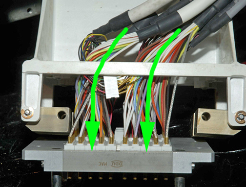
- Pull the cables through both sides of the table support holes
shown below.
Figure 5. Cable path through table support holes
- notice
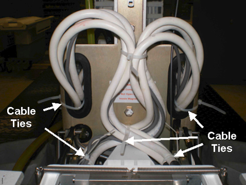
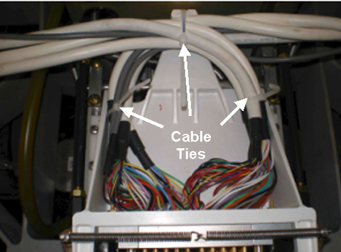
- Cut the cable tie holding the bundled cables together behind
the Connector Plate.
Figure 6. Cable tie locations
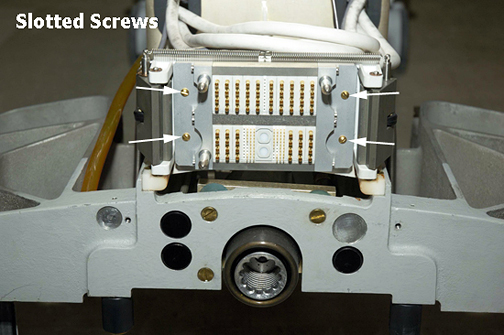
- To remove the table Connector Plate, follow these steps:
- Use a flat-blade screwdriver to remove the four screws from
the face of the Connector Plate.
Figure 7. Location of screws on the front of the connector plate
- To remove the plate and cables, guide the Connector Plate forward
with one hand while feeding the cables through the opening in the
frame assembly as shown.
Figure 8. Top View of Table Frame Assembly
- Use a flat-blade screwdriver to remove the four screws from
the face of the Connector Plate.
 |
|
Table connector plate replacement
Procedure
- Feed the cables through the opening in the frame assembly, and then lay them out to one side while holding the Connector Plate in place at the front of the frame assembly.
- Replace the four slotted screws on the face of the plate.
- Separate cables by port sides and install, without fully tightening,
three cable ties. Tie wrap ends of the cable groupings on the left
side, right side, and front of the connector plate. (Keep cable for
interlock behind the cable bundles.)
Figure 9. Cable separation with ties
- notice
- To route the cables through the table support holes, take the
right side bundle of cables and create a single loop, feed the cables
through the right side table support hole, and reconnect them to the
front side of the TIP. (Make sure the Table Top Interlock table is
behind cable loop.) Repeat the process for the left side bundle of
cables. (See Figure 5.)note: Wait to cable tie the cable bundles until the slack is checked on each coiled bundle.
- Replace both screws on each side of the TIP.
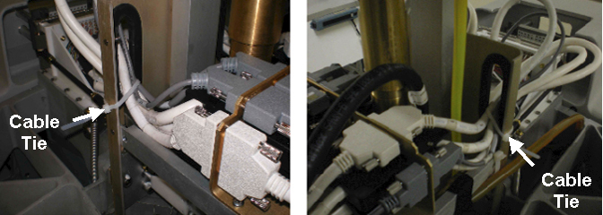
- Once the connection is made, secure the cable ties (as shown)
for proper strain relief of the cables. Trim cable ties as necessary.
Figure 10. Secure cables with cable ties
- Lift the cable loops and install the cable ties as shown in Figure 6. Trim as required.
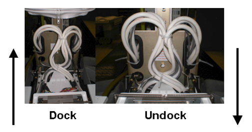
- Carefully push the frame assembly into its retracted position
while ensuring the coiled cable bundles maintain their loop without
interference. Repeat the process of manually moving the frame assembly
forward and back to confirm integrity of coiled cable bundles.
Figure 11. Cable bundles in docked and undocked frame assembly position
- Raise the table, then move the table Lock Safety Bar (shown in Figure 1) to the up position.
- Replace the front, upper and lower base covers.
- Move the table back into the Magnet Room and redock the patient table.
- Proceed to #id_15262008/SL2090374-1061609.
|
Dock connector
Dock removal from magnet room
Procedure
- Follow instructions in Dock Removal and Reinstallation to remove the dock from the Magnet Room.
- Proceed to the next section.
Dock connector plate removal
Procedure
- notice
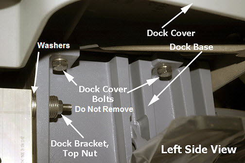
- When the dock is outside of the Magnet Room, use a 3/4-inch
wrench to remove four bolts (two on each side), and unfasten the dock
cover from the dock base.
Figure 12. Side view of dock
- Turn the dock cover upside down as shown, being careful not
to scratch the top of the cover, and set it on a protective cloth
on the floor.
Figure 13. View of upside down dock cover
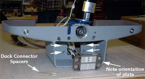
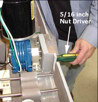
- Using a 5/16-inch nut driver, remove the four nuts from the
front of the Connector Plate.
Figure 14. Top view of dock
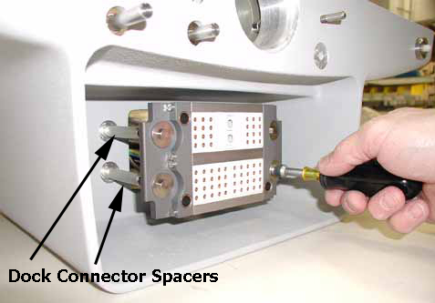
- Leave the Dock Connector Spacers attached to the dock.
Figure 15. Dock connector spacers intact
- Route the cables through the opening inside the dock cover and remove the dock Connector Plate assembly.
|
Dock connector plate replacement
Procedure
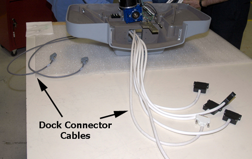
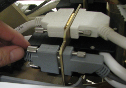
- Route the four large black connectors (two at a time) through
the opening in the dock cover, followed by the two large white connectors,
and the remaining two gray cables.
Figure 16. Dock connector cables
- Reattach the dock Connector Plate to the connector spacers on
the front of the dock, paying attention to the correct orientation
of the plate.note: Hold the dock spacer screws in place while tightening the dock Connector Plate to the connector spacers. Apply torque to the driver only, not over torquing to prevent damage to the M4 Dock Connector Bolts as they can easily shear. (See Figure 14).
- Carefully turn the dock cover right side up, reconnect the dock switch connector, and place the dock back on the dock base. Reattach the dock bolts. (See Figure 12).
Dock installation
Procedure
- Follow instructions in Dock Removal and Installation to install the dock.
- Proceed to the next step.
Replacing the Touch-n-Go (TnG) harness assembly
Procedure
- Undock the patient table and remove it from the Magnet Room.
- Remove the upper bellows, lower base cover, front upper right and front base covers as detailed in Patient Table Upper Bellows and Lower Base Side Cover Removal.
- Lower the table Lock Safety Bar, and lower the table to ensure
weight is resting on the lock bar.
Figure 17. Table lock safety bar
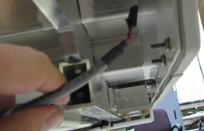
- Locate the TnG Cable assembly. To disconnect it from the switch, use your fingernail or a small flat-blade screwdriver to depress the latch on the cable side connector (as shown below), and separate the cable assembly from the TnG pigtail cable connector.
Figure 18. TnG cable with switch connector
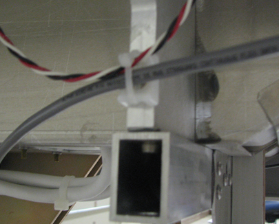
- If necessary, cut the TnG cable tie wrap.
Figure 19. Touch and Go Cable Tie Wrap
- At the Connector Mounting Plate, disconnect the cable and replace
it.
Figure 20. Connector mounting plate
- To reassemble, reverse Step 1 through Step 6.
Finalization
Procedure
- Check the operation of the Touch and Go cable assembly by establishing a landmark and scan, or by executing the TnG found on the SRI Functional Diagnostics menu.