- id_12374588
- Version: 1.4
- Date: Jul 5, 2019 10:03:32 PM
Connector Cover and Handle Hinge Replacements
Prerequisites
| Required persons | Preliminary requirements | Procedure | Finalization |
|---|---|---|---|
| 1 | Not Applicable | 60 minutes | Not Applicable |
| Item | Quantity | Effectivity | Part number | Manufacturer |
|---|---|---|---|---|
| Non-Magnetic Tool Kit | 1 | - |
5112581 |
- |
| Item | Quantity | Effectivity | Part number | Manufacturer |
|---|---|---|---|---|
| Loctite 242 | As needed. | - |
Refer to FRU Manual. |
- |
| Item | Quantity | Effectivity | Part number | Manufacturer |
|---|---|---|---|---|
| Connector Cover Hinge (non-GEM) | 1 | - |
Refer to FRU Manual |
- |
| LH Handle Hinge | 1 | - |
Refer to FRU Manual |
- |
Overview
This procedure describes how to replace the Flat Table P-Port Connector for non-GEM tables and Handle Hinge replacement for all tables.
Connector Cover Replacement
This procedure applies only to non-GEM tables.
Procedure
- Undock the table and remove it from the magnet
room.
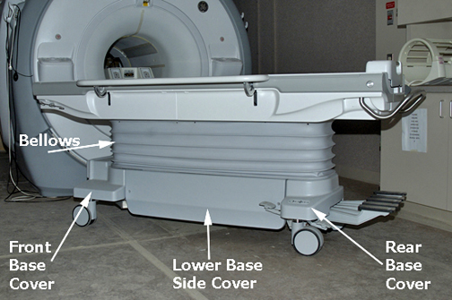
Figure 1. Table Covers
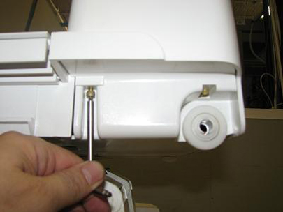
- Extend the table slide to access the rear connector section.
Remove the End Cover by removing the two screws on each side. See
illustration below.
Figure 2. End Cover Removal
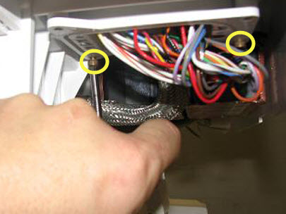
- Remove the two screws from the backside of the connector. See
illustration below.
Figure 3. Connector Screws
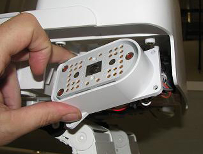
- Remove the connector from its mounting to allow for removal
of the cover. See illustration below.
Figure 4. Connector Removal
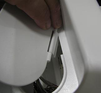
- Remove Cover Hinge by pulling it off of the
table body. See Illustration below.
Figure 5. Connector Cover Hinge Removal
- Install the new Cover Hinge.
- Assemble the table by reversing Step 1 through Step 5.
- Dock the table to the scanner and ensure proper operation.
Handle Hinge Replacement
Procedure
- Undock the table and remove it from the magnet room. See Figure 1.
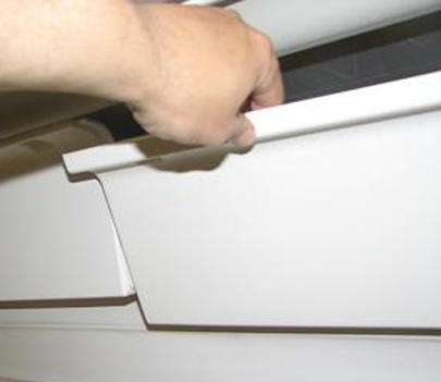
- Remove the upper-left cover by removing the bellows screws and
the cover screws that fasten the cover to the table assembly. Carefully
pull down the cover and slide it around the table handle (you may
need to remove the two upper middle cover screws adjacent to the upper
left cover to remove the upper left corner cover). See the illustration
below.
Figure 6. Upper-Left Cover Removal
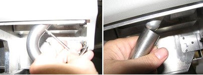
- Unscrew the Handle from the Handle Hinge. See illustration below.
Figure 7. Handle Removal
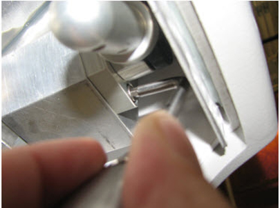
- Remove and replace Handle Hinge. Apply Loctite
to the screws when reinstalling. See illustration below.
Figure 8. Handle Hinge Removal
- Assemble the Handle and table by reversing Step 1 through Step 4.
- Dock the table with the scanner and ensure proper operation.