
- SIGNA™ Hero 3.0T Service Methods
- 5852800-8EN Revision 1.0
- 00000018WIA30E0B350GYZ
- id_20208421.12
- Aug 6, 2021 3:37:05 PM
Installing the P2/P4 cable into the dockable table cradle
Installs the cable assembly containing the P2 and P4 connectors into the dockable table cradle.
Prerequisites
| Personnel requirements | |||
|---|---|---|---|
| Required persons | Preliminary requirements | Procedure | Finalization |
| 2 | - | 30 minutes | - |
| Tools and test equipment | |||
|---|---|---|---|
| Item | Quantity | Part number | Manufacturer |
| Nonmagnetic Titanium Service Tool Kit, Small Set | 1 | 5113258 | - |
| Consumables | |||
|---|---|---|---|
| Item | Quantity | Part number | Manufacturer |
| 7.31 x 0.184 Self-Locking Cable Tie | As required | 46-208758P3 | - |
Procedure
- Install the plastic bearings and brass cable track mounting blocks onto the cable track.
Figure 1. Cable track mounting blocks 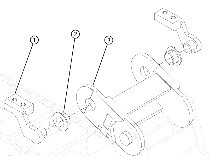
1 Brass cable track mounting block 2 Plastic bearing 3 Cable track - Install the four brass screws and four washers securing the brass cable track mounting blocks (underneath the cradle) to the bottom of the cradle.
Figure 2. Cradle cable track mount 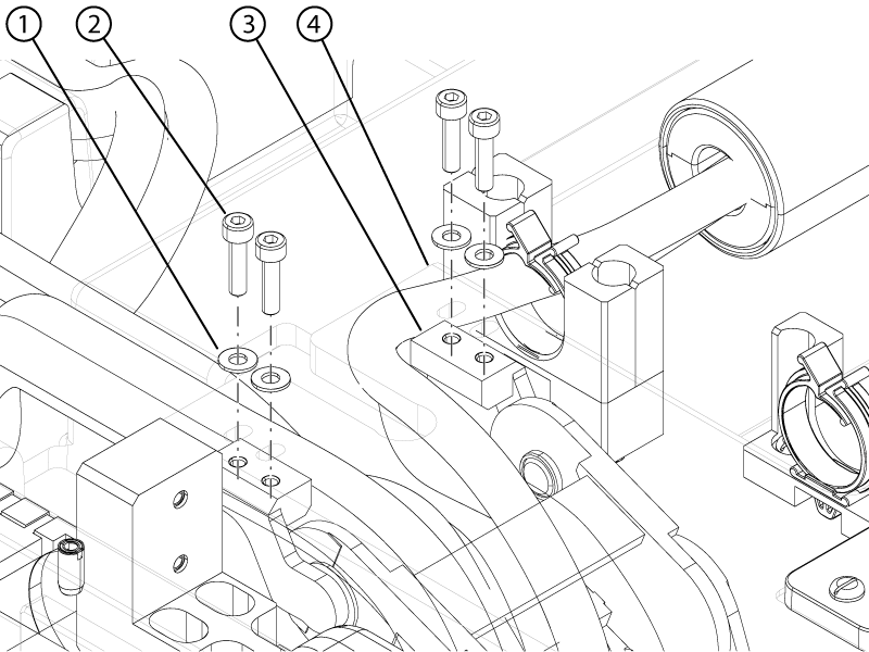
1 Brass washer 2 Brass screw 3 Brass cable track mounting block 4 Cradle bottom - Install the P4 balun into the balun holder.
Figure 3. P4 balun holder latches 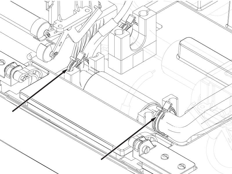
- Install the cable block into the cradle.
Figure 4. Cable block 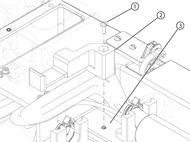
1 Brass screw 2 Cable block 3 Cradle - Connect the emergency egress connector to the emergency egress switch.
Figure 5. Handle-end cover components 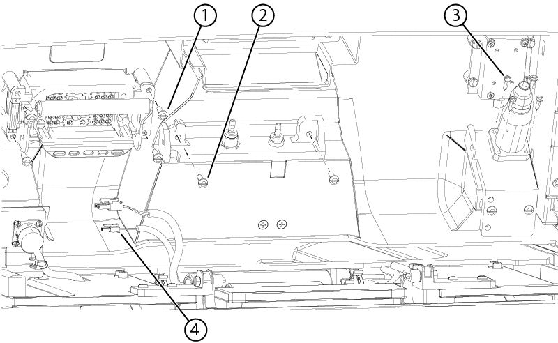
1 P4 screw 2 Pneumatic connection bracket screw 3 Peripheral Gating (PG) connector screw 4 Emergency egress connector - If previously disconnected, connect the patient alert and respiratory tubes to the pneumatic connection bracket.
Figure 6. Pneumatic connections 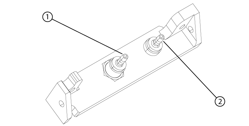
1 Respiratory tube 2 Patient alert tube - Install the two balun holders securing the P2 port cable to the cable routing track.
Figure 7. P2 cable balun holders 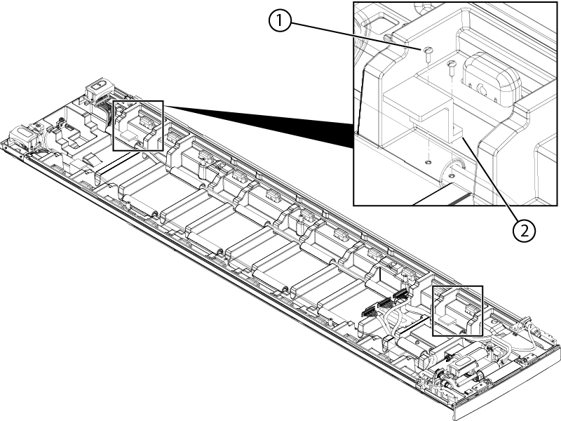
1 Screw 2 Balun holder