Installs the P1/PE cable track assembly into the dockable patient table.
Prerequisites
Personnel requirements
Required persons
Preliminary requirements
Procedure
Finalization
2
-
30 minutes
-
Tools and test equipment
Item
Quantity
Part number
Manufacturer
Nonmagnetic Titanium Service Tool Kit, Small Set
1
5113258
-
Consumables
Item
Quantity
Part number
Manufacturer
7.31 x 0.184 Self-Locking Cable Tie
As required
46-208758P3
-
Procedure
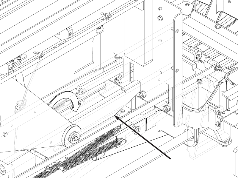
Make sure the table lock safety bar is lowered and the weight of the table is resting on it.
Figure 1. Lock safety bar down
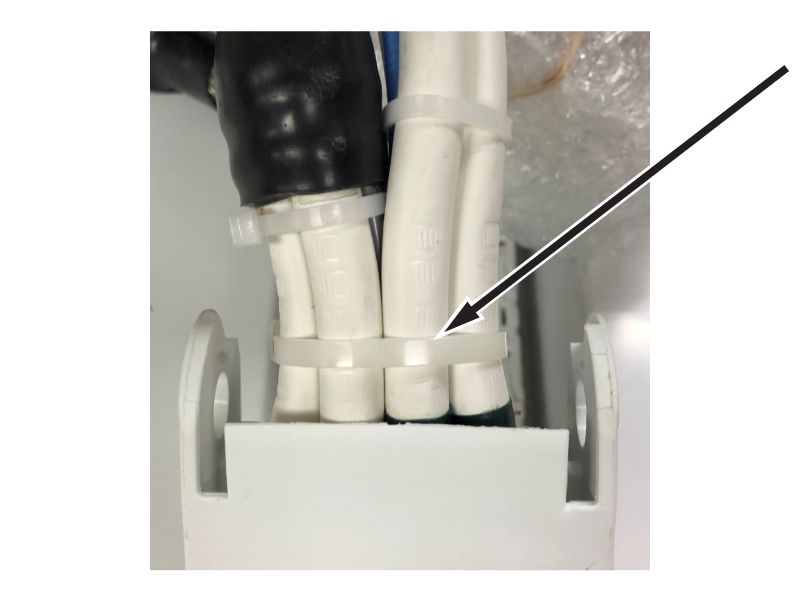
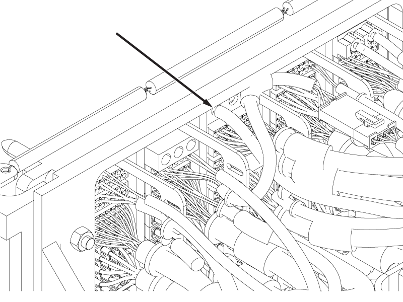
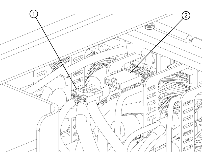
Remove the extra cable ties installed at the upper cable track end nearest to the P-port connectors for shipping. There should only be one cable tie around the entire cable bundle at the end of the cable track.
Figure 2. Upper cable track cradle end cable tie
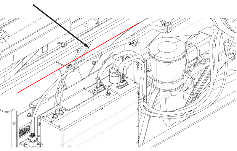
Route the ODU connectors and cables, and the lower cable track from the tabletop to the table base through the left-hand tabletop opening.
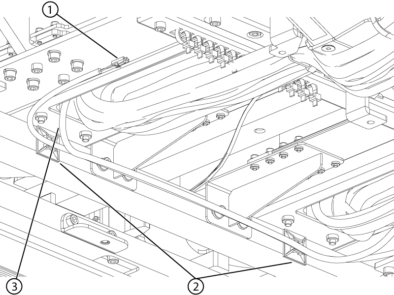
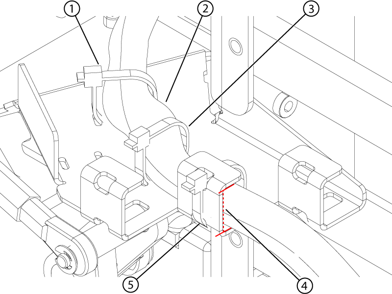
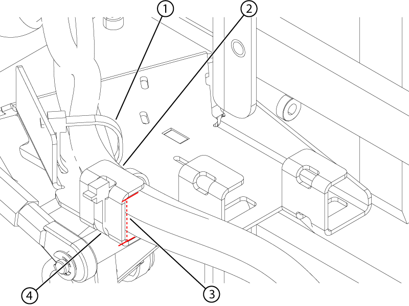
Route the Electro-CardioGram (ECG) cable from its exit at the left-hand upper cable track through the left-hand tabletop opening, and then along the left-hand Touch-and-Go (TnG) cable securing the cables to the two cable tie mounts at the bore end of the table.
Figure 3. ECG and left-hand TnG cables
1
Left-hand touch-and-go connector
2
Cable tie mounts
3
Electro-cardiogram cable
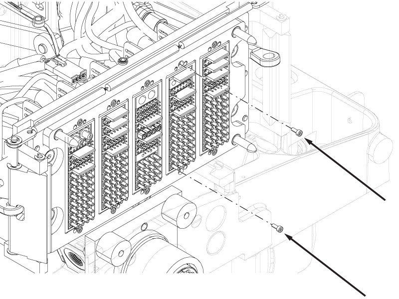
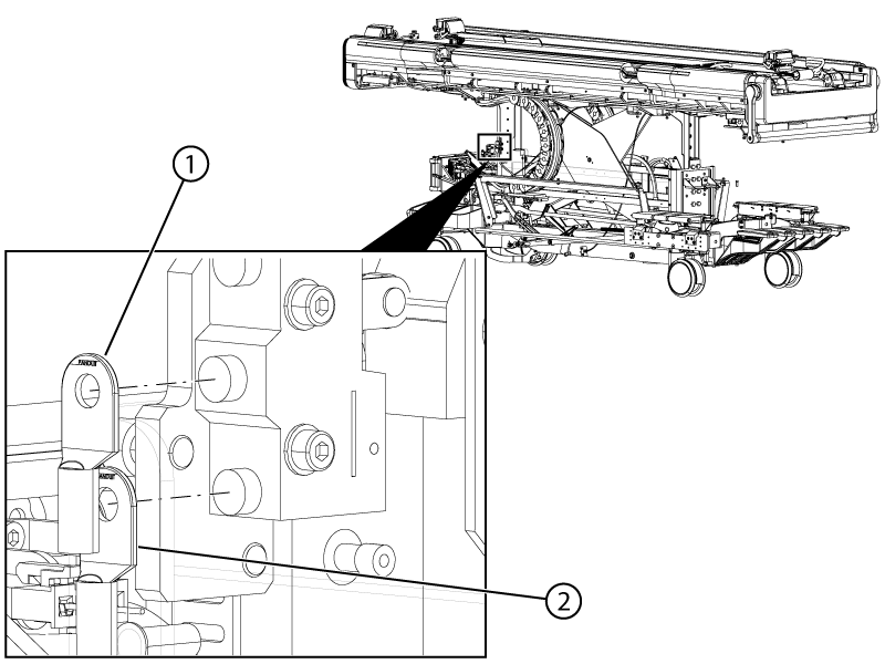
Remove the cable ties securing the cables to the left-hand upper cable track strain relief bracket.
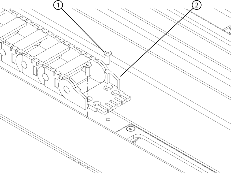
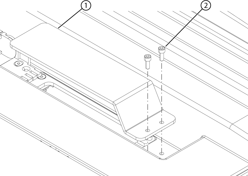
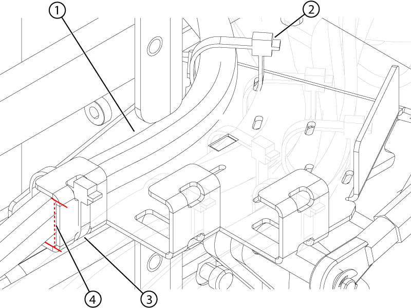
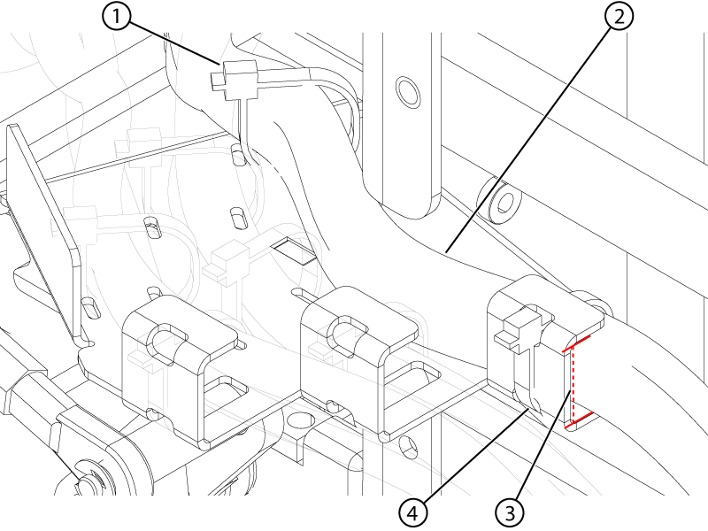
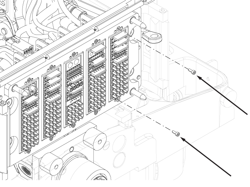
Install the two screws securing the left-hand upper cable track strain relief bracket to the top of the tabletop.
Figure 4. Left-hand upper track screws
1
Screw
2
Strain relief bracket
Install cable ties securing the cables to the left-hand upper cable track strain relief bracket in the same locations and configuration as they were removed.
Important: The cable ties must be reinstalled immediately after the strain relief bracket is secured to the tabletop. The cable ties are critical to cable track function.
Install the two screws securing the left-hand cable protection plate to the tabletop.
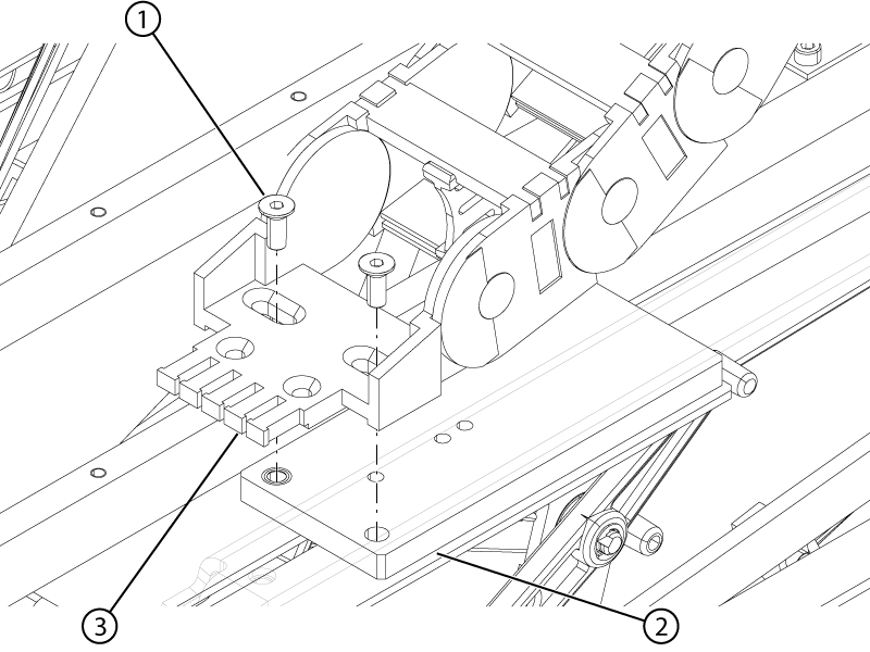
Install the two screws securing the left-hand lower cable track strain relief bracket to the bottom of the tabletop.
Figure 6. Left-hand lower track upper screws
1
Strain relief bracket
2
Screw
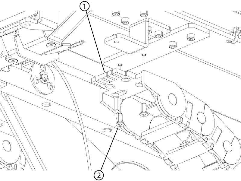
Install the two screws securing the left-hand lower cable track strain relief bracket to the slider plate.
Figure 7. Left-hand lower track lower screws
1
Screw
2
Slider
3
Strain relief bracket
Install the P1, P3, and PE ODU connectors to the ODU plate.
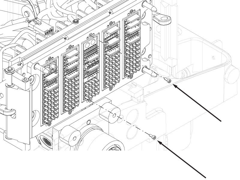
Install the two screws securing the P3 ODU connector to the ODU plate.
Important: Do not overtighten the ODU screws. Tighten one-half turn past free-spinning. Overtightening may affect the alignment of the connector and result in damage to the pins.
Figure 8. P3 ODU screws
Route the following cables from the P3 ODU in the right-hand inner cable bracket.
Install the cable tie securing the cables to the right-hand inner cable bracket as shown.
Important: Make sure the cables and the cable tie(s) are within the inner radius of the cable bracket. Cable(s) or cable tie(s) outside of the inner radius may interfere with table operation or damage the cable(s).
Route the remaining cables from the P3 ODU in the left-hand inner cable bracket.
Figure 10. Left-hand inner cable bracket
1
Front cable tie
2
Left-hand inner cable route
3
Bracket inner radius
4
Bracket cable tie
Install cable tie(s) securing the cables to the left-hand inner cable bracket.
Important: Make sure the cables and the cable tie(s) are within the inner radius of the cable bracket. Cable(s) or cable tie(s) outside of the inner radius may interfere with table operation or damage the cable(s).
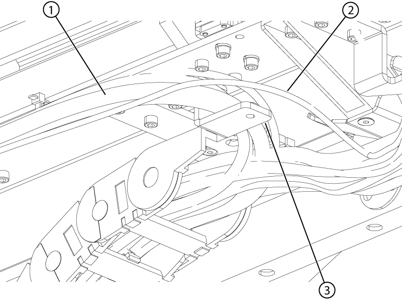
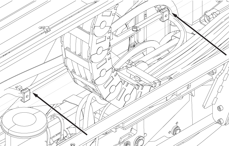
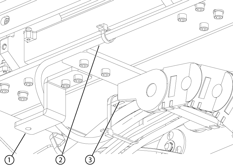
Route the following cables in the right-hand lower cable track, exiting the track at the top of the track and routing around the bellows cover bracket as shown.
Motor power
Motor signal
String encoder
Note: Open the right-hand lower cable track to route the cables if it is not already open.
Figure 11. Motor and string encoder cable routing
1
Motor and string encoder cables
2
Dummy load cable
3
Bellows cover bracket
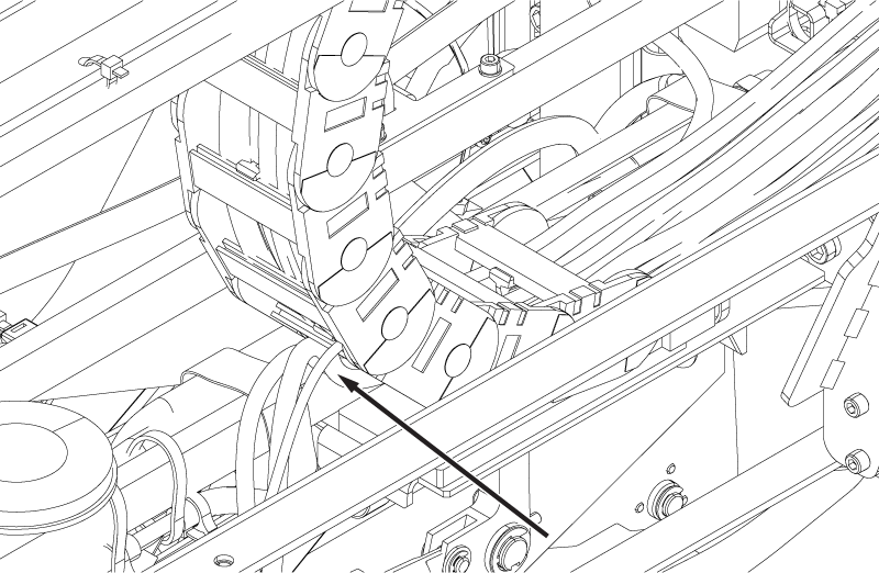
Route the ECG cable in the right-hand lower cradle track from the upper opening to the lower exit.
Route the PAC fiber optic cable through the track to exit the back of the track where the PAC 1-wire and PAC power cables exit.
Figure 12. PAC cable track exit
Close the right-hand lower cable track.
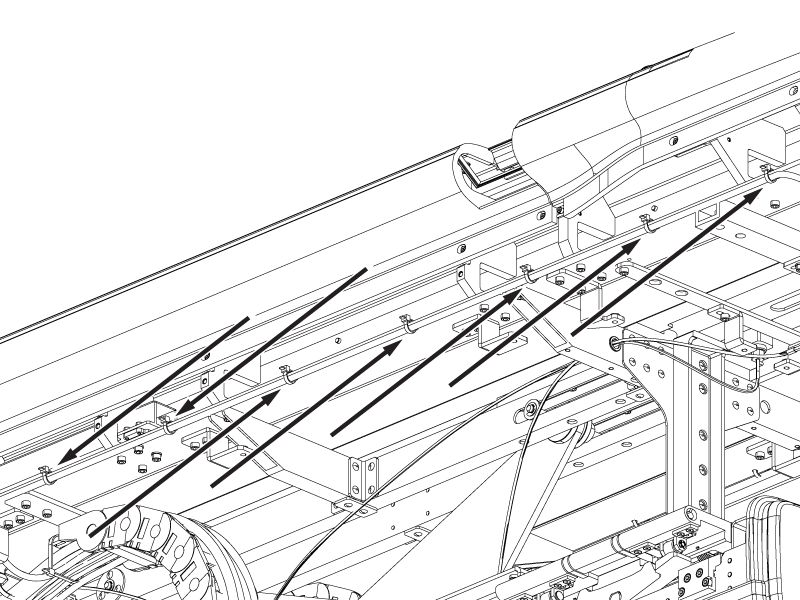
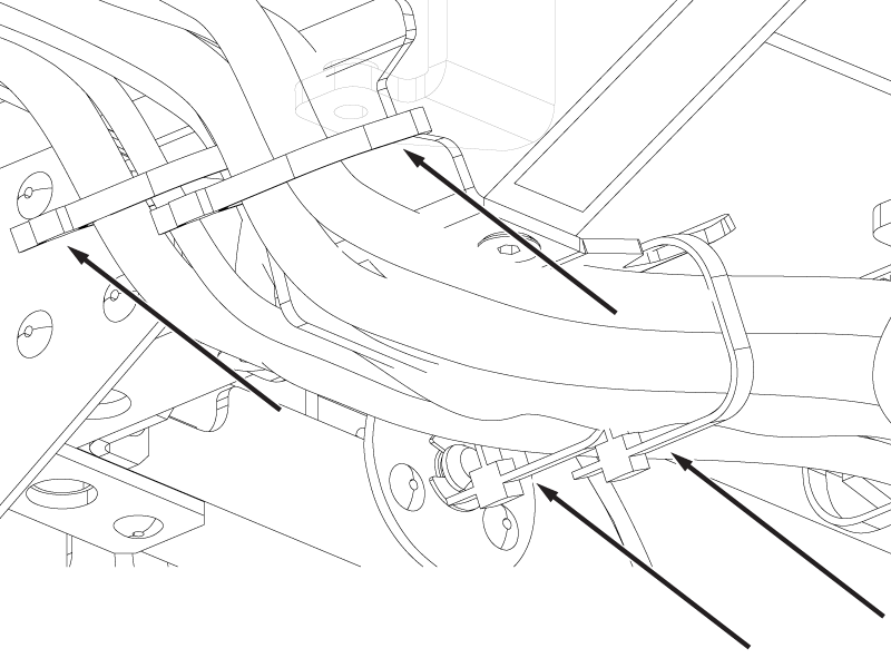
Route the two motor cables and the string encoder cable with the dummy load cable along the side of the table, installing cable ties as shown below.
Figure 13. Motor and dummy load cable tie locations
Connect the motor power, motor signal, and string encoder connectors.
Install cable ties securing the motor and signal encoder connectors to the cable tie mounts on the bottom of the tabletop.
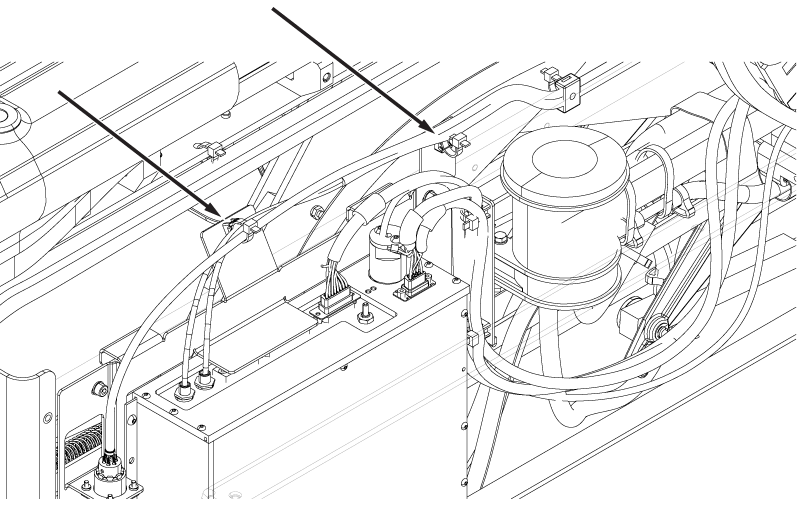
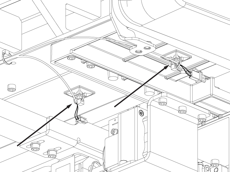
Route the ECG cable along the PhotoPlethysmoGraphy (PPG) cable on the inside of the support bar to the PAC and install cable ties securing the cables to cable tie mounts on the bar.
Figure 14. PAC ECG and PPG cable tie mount locations
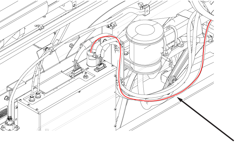
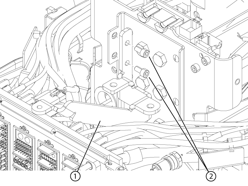
Route the PAC fiber optic along the existing PAC cables through the PAC mounting plate to the PAC as shown.
Figure 15. PAC fiber optic cable route
Connect the ECG cable to the PAC ECG connector and the PAC fiber optic cable to PAC connector J1.
Secure the PAC cables to the PAC mounting plate with cable ties.
Figure 16. PAC mounting plate ECG and PPG cable tie mounts
Make sure that all of the PAC cables are routed below the edge of the PAC mounting bracket as shown.
Figure 17. PAC bracket edge line
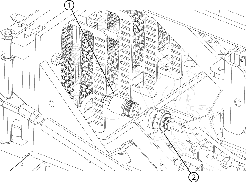
Connect the patient alert tube to the top left (as viewed from the rear) side of the P3 ODU connector.
Figure 18. Patient alert ODU connection
Install the two screws securing the P1 ODU connector to the ODU plate.
Important: Do not overtighten the ODU screws. Tighten one-half turn past free-spinning. Overtightening may affect the alignment of the connector and result in damage to the pins.
Figure 19. P1 ODU screws
Route the cables from the P1 ODU in the left-hand middle cable bracket.
Figure 20. Left-hand middle cable bracket
1
Front cable tie
2
Left-hand middle cable route
3
Middle cable tie
4
Bracket inner radius
5
Bracket cable tie
Install cable tie(s) securing the cables to the left-hand middle cable bracket.
Important: Make sure the cables and the cable tie(s) are within the inner radius of the cable bracket. Cable(s) or cable tie(s) outside of the inner radius may interfere with table operation or damage the cable(s).
Connect the P2 bone conducting headphone cable to the P1 ODU headphone connector.
Figure 21. P2 bone conducting headphone connection
1
P2 bone conducting headphone
2
P1 headphone
Install the two screws securing the PE ODU connector to the ODU plate.
Important: Do not overtighten the ODU screws. Tighten one-half turn past free-spinning. Overtightening may affect the alignment of the connector and result in damage to the pins.
Figure 22. PE ODU screws
Connect the P2 blue RF Tx cable from the P2 ODU connector to the P1 transmit connector from the P1 port.
Figure 23. P1 transmit connection
1
P2 RF Tx
2
P1 transmit
Route the cables from the PE ODU in the left-hand outer cable bracket.
Figure 24. Left-hand outer cable bracket
1
Front cable tie
2
Left-hand outer cable route
3
Bracket inner diameter
4
Bracket cable tie
Install cable tie(s) securing the cables to the left-hand outer cable bracket.
Important: Make sure the cables and the cable tie(s) are within the inner radius of the cable bracket. Cable(s) or cable tie(s) outside of the inner radius may interfere with table operation or damage the cable(s).
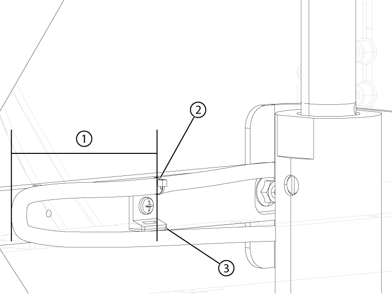
Route the up-limit switch cable from the PE ODU connector to the left-hand support bar and secure the cable to only one loop of the cable tie mount on the inside of the bar.
Important: Make sure there is at least 25 mm (1 inch) of slack behind the cable tie mount with the electrical sled all the way forward.
Important: Make sure the cable is tightly tied to only one loop of the cable tie mount.
Figure 25. Up-limit switch cable tie mount
1
Minimum 25 mm (1 inch)
2
Cable tie
3
Cable tie mount
Connect the terminal lugs of the up-limit switch cable to the up-limit switch. Make sure the terminals are oriented vertically and the black lug is connected to the middle terminal, and the red lug is connected to the lower terminal.
Figure 26. Up-limit switch terminal lugs
1
Black
2
Red
Install the base cover bracket.
Figure 27. Base cover bracket
1
Bracket
2
Screws
Install the two screws securing the base cover bracket to the table.
Route the home switch and clutch signal cable from the top of the lower left cable track around the bellows cover bracket and along the side of the table towards the handle end of the table.
Figure 28. Home switch and clutch signal cable route start
1
Bellows cover bracket
2
Home switch and clutch signal cable
3
Left-hand lower cable track upper exit
Install cable ties securing the home switch and clutch signal cable to the tabletop.
Figure 29. Home switch and clutch signal cable ties
Connect the home switch connector to the home switch.
Connect the clutch signal connector to the electro-magnetic clutch.
Install cable ties securing the home switch and clutch signal cables to the cable tie mounts on the tabletop.
Figure 30. Home switch and electro-magnetic clutch cable tie mounts
Push the cables in the left-hand lower cable track such that the cable slack is at the top exit of the track.
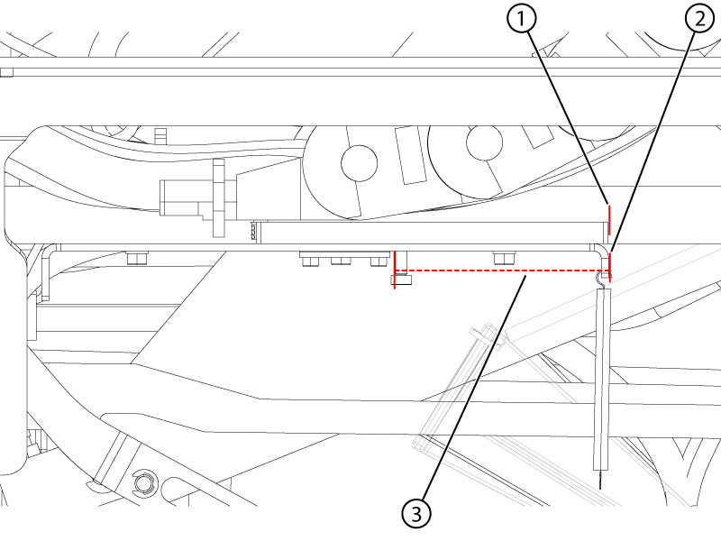
While holding the slack at the top exit of the track, adjust the position of the slide plate until the edge of the slide plate is aligned with the edge of the support bracket. Make sure the distance between the spring mounting locations shown is 90 ± 5 mm from outer end to outer end.
Figure 31. Slide plate alignment
1
Slide plate edge
2
Support bracket edge
3
Spring mounting distance
When the distance is within tolerance, install four cable ties securing the cables to the end of the cable track plate. Split the cable into two approximately equal bundles and install two of the cable ties on each half bundle.
Figure 32. Half-bundle cable tie locations
Install the spring onto its support.
Install two cable ties securing the cables to the top exit end of the cable track, one cable tie per half bundle.
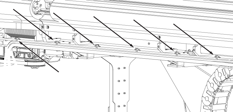
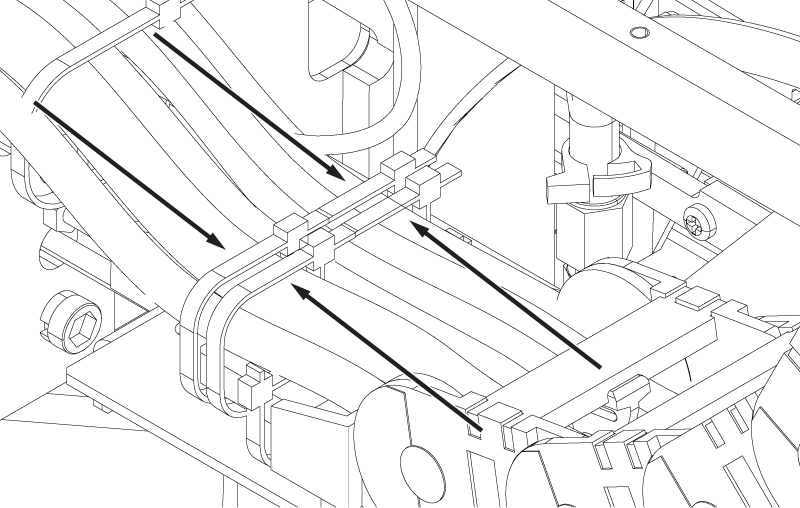
Route the slack of the cables exiting the top of the lower cable track forward and install four cable ties securing the cables to the cross-beam cable bracket. Install one cable tie on each half bundle at each end of the bracket.
Important: Make sure the cables are within the outer edges of the bracket. Cable(s) or cable tie(s) outside of the edges of the bracket may interfere with table operation or damage the cable(s).
Figure 33. Bracket cable tie locations
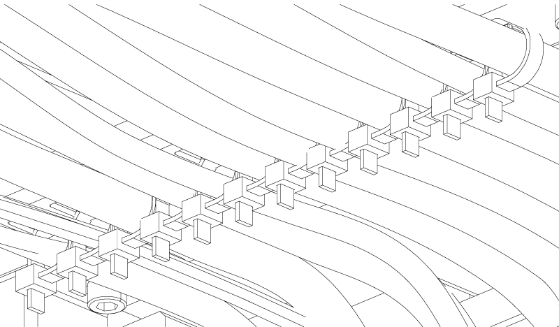
Install cable ties securing the cables to the multiple cable tie bracket. Secure one white cable per cable tie and two smaller cables per cable tie.
Note: For ease of installation:
Loosely install the cable tie around the cable(s).
Slide the cable tie onto the bracket hook.
Hold the square portion of the cable tie while pulling the cable tie tight.
Important: Pulling the cable tie tight without holding it may cause the bracket hook to bend.