
- Discovery MR750 3.0T System Service Methods
- 5690009-2EN Revision 4
- 00000018WIA30D2DE20GYZ
- id_131058572.0
- Feb 22, 2021 1:47:12 AM
3.0T HD 8-Channel Torso Array Coil FRUs and Cable Replacements
Prerequisites
| Required persons | Preliminary requirements | Procedure | Finalization |
|---|---|---|---|
| 1 | Not Applicable | 30 minutes | Not Applicable |
| Item | Quantity | Effectivity | Part number | Manufacturer |
|---|---|---|---|---|
| Standard tool kit | 1 | - | - | - |
| Pair of tweezers | 1 | - | - | - |
| Item | Quantity | Effectivity | Part number | Manufacturer |
|---|---|---|---|---|
| GE 3.0T HD 8-Channel Torso FRU Cable | 1 | - |
2416958 | - |
About this task
This document contains the procedure for replacing the cable assembly on the 3.0T HD 8-Channel Torso Coil by GE/USAI, catalog M3335LN.
Cable Removal
Procedure
Notice Note:Remove the coil center cover by removing all the screws around its perimeter.This procedure applies to either anterior or posterior.
Figure 1. Center Cover 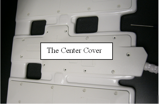
- Check the connection of the cable assembly in the coil.
Figure 2. Cable Interface 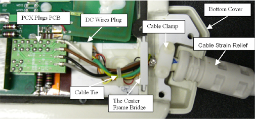
- Disconnect the PCX plug PCB (with 4 PCX connectors) on the cable
end.
Figure 3. Disconnect PCX Plugs 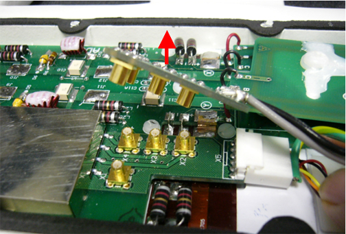
- Using a flat screwdriver and tweezers, disconnect the DC plug
on the cable end from the center board.
Figure 4. Disconnect DC Plug 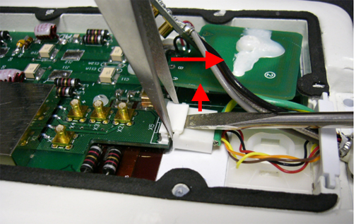
- Remove the center frame bridge that holds the cable assembly.
Figure 5. Remove Center Frame Bridge 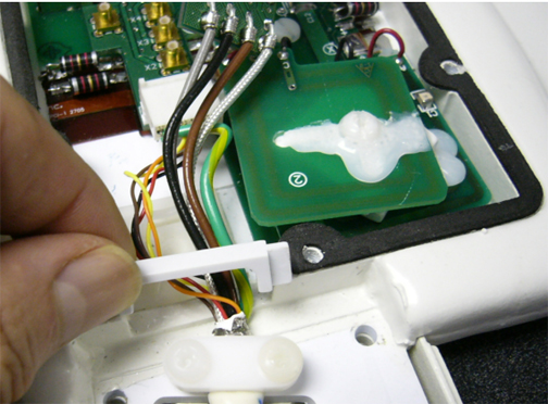
- Remove the cable clamp (with two screws) that holds down the
cable assembly.
Figure 6. Remove Cable Clamp 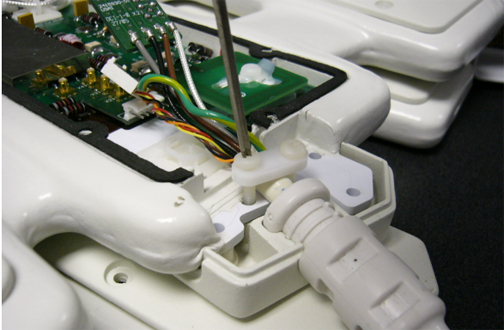
Cable Installation
Procedure
- Note:Seat the bottom cover (with cable cradle) in the proper position.
The new cable has two cable ends with the PCX connectors on the board. The longer one is for the anterior package (without Velcro belt). The short one is for the posterior package (with Velcro belt mounted). The installation procedure is the same for both cables.
Figure 7. Seat Bottom Cover 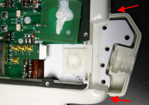
- Put the new cable assembly into the coil.
Figure 8. Place New Cable Assembly into Coil 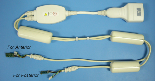
- Ensure the cable strain relief matches the notch of the cradle,
and ensure the cable connector end sits level and upright. (The side
with “Do not loop” label of the in-cable box should face
up. If it does not face down, rotate the strain relief.)
Figure 9. Level Cable Connector End 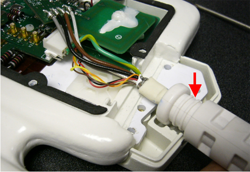
- Connect the DC plug to the corresponding receptacles on the
center board.
Figure 10. Connect DC Plug 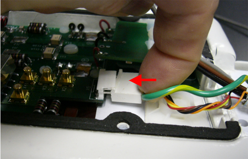
- Put on the cable clamp holding the cable. Tighten the cable
clamp with the two screws.
Figure 11. Tighten Cable Clamp 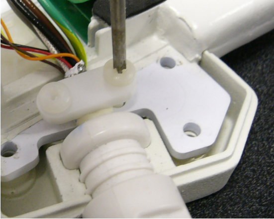
- Close and screw the coil center cover onto the coil. Scan the
coil to ensure proper assembly.
Figure 12. Connect Center Cover 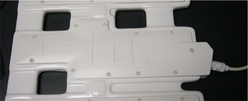
Field Replaceable Units
About this task
Refer to the following table for FRUs and replaceable accessories.
| FRU Description | GEHC Part # |
| FRU, GE 3.0T HD Torso Array Coil, Anterior (non-RoHS) | 2418063 |
| FRU, GE 3.0T HD Torso Array Coil, Anterior (RoHS) | 5498925 |
| FRU, GE 3.0T HD Torso Array Coil, Posterior (non-RoHS) | 2418064 |
| FRU, GE 3.0T HD Torso Array Coil, Posterior (RoHS) | 5498926 |
| FRU, GE 3.0T HD CTL Array, Cable | 2416958 |
| FRU, 3.0T 8-Channel Torso Phantom | 2381683-3 |
| FRU, 3.0T 8-Channel Torso Phantom Positioner | 2381683-4 |
| FRU, Patient Liner | 2381683-5 |
| FRU, Phantom Kit | U1-155205 |
| TL Unified Phantom | 5343347-2 |
| Accessory Description | GEHC Part # |
| FRU, Patient Pad | 2416959 |
Finalization
Finalization
No finalization steps.