- Discovery MR750 3.0T System Service Methods
- 5690009-2EN Revision 4
- 00000018WIA30113B10GYZ
- id_20069328.2
- Jul 13, 2021 3:56:31 PM
Setting up Adaptive Image Receive (AIR) Anterior Array (AA) for MCQA
Set up the Adaptive Image Receive (AIR) Anterior Array (AA) for the Multi-Coil Quality Assurance (MCQA) check.
Prerequisites
Note: Coils do not ship with phantoms. Phantoms come in a unified phantom set with the system.
| Personnel requirements | |||
|---|---|---|---|
| Required persons | Preliminary requirements | Procedure | Finalization |
| 1 | - | 30 minutes | - |
| Tools and test equipment | |||
|---|---|---|---|
| Item | Quantity | Part number | Manufacturer |
| TL Unified Phantom (for 3.0T) | 2 | 5343347-2 | - |
| PA Phantom Positioner for Both 1.5T and 3.0T | 1 | 5405748 | - |
| Air Anterior Array (AA) Coil FRU | 1 | 5030190 | - |
| Air Anterior Array (AA) Coil Redesign | 5030192 | Requires 28.0_R05 and above | |
| Anterior Array (AA) Strap FRU | 1 | 5503457 | - |
| Safety |
|---|
|
Before working in any GE Healthcare MR suite or performing any GE Healthcare service procedure, you must:
If you have any safety concerns at any time, do not begin work or immediately stop work and move to a safe location. Immediately contact your supervisor or site safety officer for instructions on how to proceed. |
Procedure
- Put the flat filler panel on the table.
Figure 1. Flat filler panel 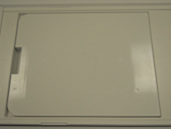
- Do the following steps:
- Place two TL unified phantoms on the table, positioned with the long axis in the left/right direction such that the laser light crosshair is centered between the two phantoms. There should be no air gap between the phantoms.
Figure 2. TL unified phantoms 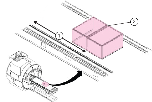
1 1080 mm 2 Landmark position
- Place two TL unified phantoms on the table, positioned with the long axis in the left/right direction such that the laser light crosshair is centered between the two phantoms. There should be no air gap between the phantoms.
- Put the PA phantom positioner onto the two TL unified phantoms with the notch facing the bore. Make sure there are two patient straps positioned on each side of the table.
Figure 3. Positioning of PA phantom positioner 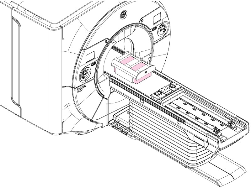
- Do the following steps to set up the AIR AA coil:
- Put the AIR AA coil on top of the posterior array (PA) phantom positioner, aligning the laser light to the crosshairs at the center (or GE logo) on the coil to the existing landmark at 1080 mm.
- Secure the coil to the positioner with Velcro straps. The straps should go over the tick marks on the coil.
- Connect the coil to port .
Figure 4. Tick marks on coil 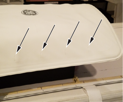
Figure 5. Securing coil to positioner 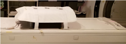
- If directed to do so on the in-room display, set the center position of the AIR AA coil connected on port using the Touch-and-Go strips on the side of the table.
Figure 6. Setting center position of AIR AA coil using Touch-and-Go 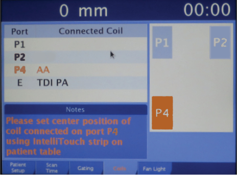
- Landmark the AIR AA coil at the crosshair mark and press Advance to Scan.
Figure 7. Landmarking on AIR AA coil 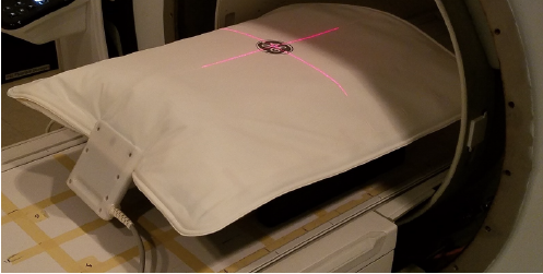
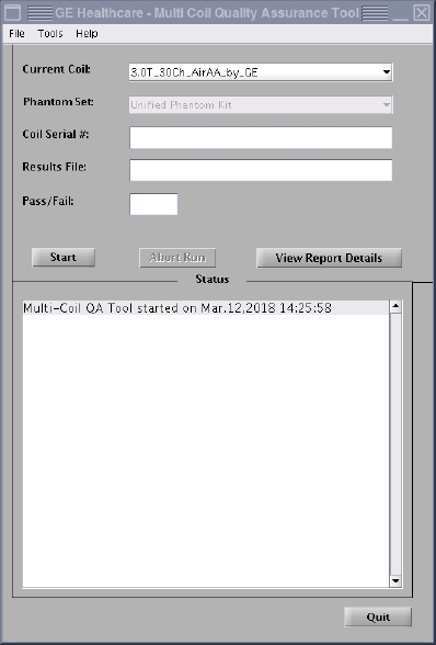
- Run the MCQA check.Note: Select 3.0T_30Ch_AirAA_by_GE (or equivalent platform option) in the Current Coil field.
Figure 8. MCQA tool menu