Basic Service Documentation. Copyright General Electric Company.
Object ID: 00000018WIA30B24840GYZ
Topic ID: id_2014881 Version: 4.1
Date: Jun 7, 2021 3:46:36 PM
Removing the host computer - Dell T5820
Remove the host computer.
Prerequisites
Personnel requirements
Required persons
Preliminary requirements
Procedure
Finalization
1
-
30 minutes
-
Tools and test equipment
Item
Quantity
Part number
Manufacturer
Screwdriver
1
-
-
Disk Management Tool
1
-
-
ESD Strap
1
-
-
Procedure
If installed, disconnect the optional UPS.
For added protection, disconnect the twist-n-lock main power cable from the rear of the console.
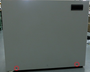
Remove the two screws that secure the left side panel of the GOC.
Figure 1. GOC left side panel
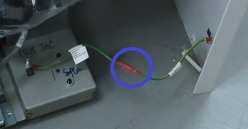
Note: The side panel has a short ground lead connecting it to the main chassis. When removing the side panel, do not strain this ground lead.
Disconnect the short ground lead that connects the side panel to the GOC main chassis at the center of the lead.
Figure 2. Left side panel ground lead
Remove the left side panel and put it in a safe place.
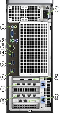
Make sure all the cables are properly labeled. If not, note their locations for reattachment.
Figure 3. Dell T5820 cable configuration
Table 1. Dell T5820 cable configuration
Item
Run #
Description
1
NA
GOCAA (line in, line out)
2
NA
Site ethernet
3
E3048
To Keyboard USB port
4
NA
Mouse USB cable
5
E3037
To system cabinet top J25
6
NA
1-wire Adapter
7
NA
Brainwave on host (optional)
8
E3046
To LCD monitor
9
NA
Power cable
11
E3502
To System Cabinet Top J63
Remove all the cables connected to the computer.
Remove the strap(s) from the computer.
Remove the host computer from the GOC.
Loosen or remove the brackets if necessary.
When replacing the host computer or hard drives, do a disk wipe on all applicable hard drives. For more information, refer to the latest revision of the Disk Management Tool Service Manual (5500610-1EN) available from the online documentation library.

 Note: The side panel has a short ground lead connecting it to the main chassis. When removing the side panel, do not strain this ground lead.