
- SIGNA MR355 / SIGNA MR360
- Service Manual
- 5856356-3EN Revision 5.0
- Basic Service Documentation. Copyright General Electric Company.
- 00000018WIA30B48F20GYZ
- id_131062202.0
- Jul 19, 2019 11:00:19 AM
Body and Head Maximum Power Setup and Calibration
Prerequisites
| Required persons | Preliminary requirements | Procedure | Finalization |
|---|---|---|---|
| 1 | Not Applicable | 45 minutes | 5 minutes |
| Item | Quantity | Effectivity | Part number | Manufacturer |
|---|---|---|---|---|
| Screwdriver, slotted (long & narrow) | 1 | - | - | - |
| 100 MHz Scope (equivalent or greater) | 1 | - |
46-183029P61 | - |
| RF Power Measurement Kit | 1 | - |
46-317724G1 or G2 | - |
| 50 ohm, 200 Watt, 30dB Attenuator (dummy load) | 1 | - |
46-317724P14 | - |
| RF Test Cables Kit | 1 | - |
46-255816G1 | - |
| Digital Multimeter (DMM) | 1 | - |
46-194427P49 | - |
| DMM Test Cable - BNC to Banana (optional) | 1 | - |
2239139 | - |
| 7/16(M)-N(F) Adapter | 1 | - |
5166139 | - |
| Excite 3 RF System Cabinet SV Cable Kit | 1 | - |
5117087 | - |
| ||||||||||||||||
| Condition | Reference | Effectivity |
|---|---|---|
|
Recommended Warming Time: Exciter - 20 minutes | - | - |
|
The DTx Exciter is outputting enough power for the system to meet the rated head and body RF output power levels (DTx Exciter describes how to check the DTx Exciter output.). | - | - |
|
The preferred method for the RF Amplifier calibration is to use the Power Measurement kit that is mentioned in this procedure. If this kit is not available, RF output can be calibrated using an Alternative Equipment Setup and Dummy load and Cables Calibration. | - | - |
|
The oscilloscope input channel correction factor is known when the scope bandwidth is < 300 MHz and the wattmeter is not being used. See Scopes with Less than 300MHz Bandwidth. | - | - |
About this task
Overview
This procedure describes how to calibrate the CSA in a 1.5T system.
Calibration is done to prevent faults and to make sure that the CSA is outputting the specified 10kW of RF body power and 2kW of RF head power. Adjustments may need to be made if Exciter and/or CSA has been replaced or if any of the measurements taken during the check are found not to meet specifications. References are referred to in the procedure and provide extra information and directions to assist the user with accomplishing the RF power measurement task. General Troubleshooting provides helpful troubleshooting information in the event that a problem is encountered during the RF power check or calibration.
The Body and Head Gain pots are in series with each other. The Body Gain pot is first in the series. The Head Gain pot is factory set so that the head gain is 7dB less (63 dBm) than the body gain (70 dBm).
Disabling TR, DD, and RF Input
Procedure
- On the front of the Driver Module Lite, disable T/R error reporting
by setting the TR and DD switches to the DISABLE (disable faults)
position.
Figure 1. Driver Module Switch 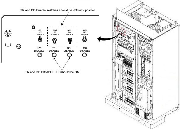 Note:
Note:HV should remain set to Enable.
- Place the RF Enable switch on the DTX Exciter, located in the
top of the System cabinet, into the Disable (down) position. See Figure 2.
Figure 2. RF ENB Switch 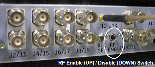
Setting up
Procedure
Body RF Output Power Calibration
Procedure
- If using the RF Power Measurement Kit then refer to the RF
Power Measurement Kit laminated card set.
- If using the scope (NOT the RF Power Measurement Kit) to measure power then refer to Alternate Equipment Setup for the proper system body configuration.
Scan Setup (Body)
Procedure
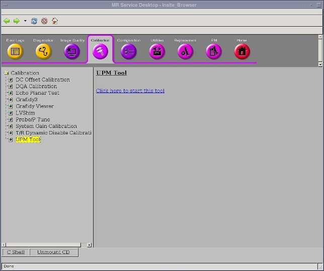
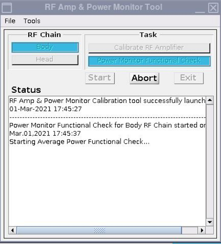
- Open service browser. Go to calibration UPM Tool Choose “Click
here to start this tool”
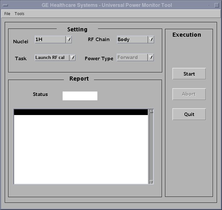
- The calibration tool will open. Please choose task as “Launch
RF cal” and RF Chain as “Body”. Clink “Start”
(For System running before SV29.1/SV25.4)
(For System running SV29.1/SV25.4 or later)
Adjusting the RF Amplifier Output Power (Body)
Procedure
- Verify the Unblank LED on the front of the CSA Module is ON.
Figure 3. POT locations on CSA module 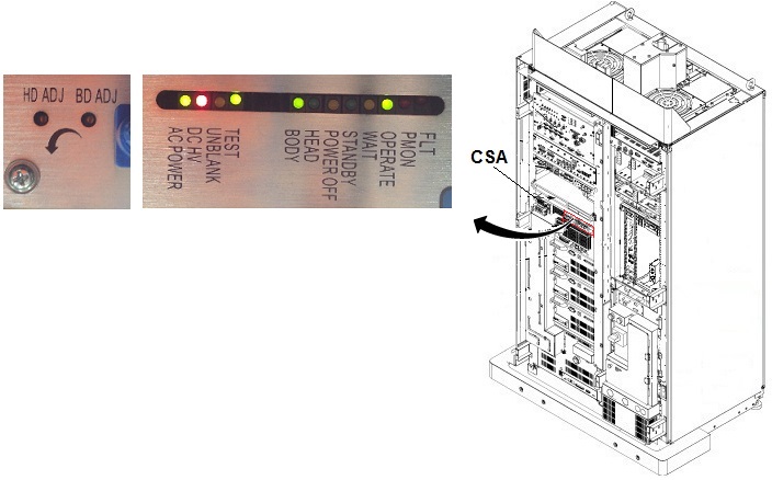
- If using the RF Power Measurement Kit, refer to the specified
number of divisions printed on the RF Power Measurement Kit card 72
(1.5T Body RF Output) needed to achieve 10kW of RF power output.
Adjust the Body Gain pot on the front of the CSA so that the RF waveform
displayed on the scope meets, but does not exceed, this number of
divisions. See Figure 4.Note:
Card 72 is for 16kW(72dBm) RF Amp. For 10kW(70dBm) RF Amp, it is required to set rotary attenuator to the value on the card - 2dB. For example, if the card shows '8dB', then set to '6dB'.
Figure 4. How to re-configure Card72 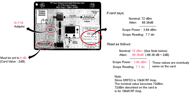
- If using the oscilloscope procedure (NOT the RF Power Measurement Kit) then read the peak voltage (Vpeak) from the scope display and use the formula below or the Power Calculator Tool Power Calculator Tool to calculate the RF output power. The dummy load and cable loss factors were determined from the procedure in Dummy Load and Cables Calibration. The scope correction factor was determined in Scopes with Less Than 300 MHZ Bandwidth . Adjust the Body Gain pot on the front of the CSA until the RF output calculated from the formula meets, and does not exceed, the 10kW (70dBm) specification. See Figure 3.
Table 5. RF Power Measurement (in watts) Using Oscilloscope And Formula 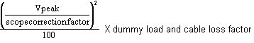
Head RF Output Power Calibration
About this task
Do not perform head output power calibration until body output calibration has been completed.
Procedure
- If using the RF Power Measurement Kit then refer to the RF Power
Measurement Kit laminated card set.
- Confirm that the rotary attenuator is set to the correct position
indicated on the card. Note:
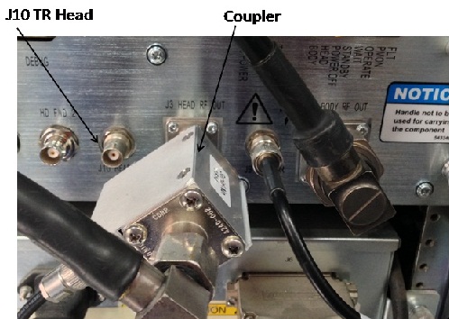
To connect the coupler to Head output port, there is a conflict with the cable connecting with J10 HEAD TR.
Remove the cable from J10 and connect first, then connect coupler to Head Output. Then, restore the cable to J10.
- Confirm that the rotary attenuator is set to the correct position
indicated on the card.
Scan Setup (Head)
Procedure
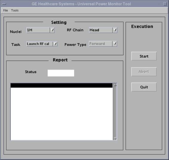
- The calibration tool will open. Please choose task as “Launch
RF cal” and RF Chain as “Head”. Clink “Start”.
(For System running before SV29.1/SV25.4)
(For System running SV29.1/SV25.4 or later)
Adjusting the RF Amplifier Output Power (Head)
Procedure
- If using the oscilloscope procedure (NOT the RF Power Measurement Kit) then read the peak voltage (Vpeak) from the scope display and use the formula below or the Power Calculator Tool to calculate the RF output power. The dummy load and cable loss factor was determined from the procedure in Dummy Load and Cable Calibration. The scope correction factor was determined in Scopes with Less Than 300 MHz Bandwidth. Adjust the Head Gain pot on the front of the CSA module until the RF output calculated from the formula meets, and does not exceed, the 2kW (63dBm) specification. See Figure 3.
Table 6. RF Power Measurement (in watts) Using Oscilloscope And Formula: