
- SIGNA™ Hero 3.0T Service Methods
- 5852800-8EN Revision 1.0
- 00000018WIA30C9FA40GYZ
- id_20164634.0
- Nov 2, 2021 1:14:23 PM
Running ICW Installation Mode
The Installation and Calibration Wizard provides an interface to navigate through required system procedures, checks, and calibrations.
Prerequisites
| Personnel requirements | |||
|---|---|---|---|
| Required persons | Preliminary requirements | Procedure | Finalization |
| 1 | - | Varies | - |
| Required conditions |
|---|
| Make sure all customer-purchased options are installed before running ICW. Any options added after running ICW will not be displayed. |
| A service key is required to launch the Installation and Calibration Wizard. |
| Safety |
|---|
|
Before working in any GE Healthcare MR suite or performing any GE Healthcare service procedure, you must:
If you have any safety concerns at any time, do not begin work or immediately stop work and move to a safe location. Immediately contact your supervisor or site safety officer for instructions on how to proceed. |
About this task
ICW installation mode is used for new installations and upgrades.
- The left pane lists all tasks required to complete the installation.
- Tasks must generally be completed in order, from top to bottom (tasks with prerequisites are grayed out until all prerequisites are completed). Non-grayed out tasks may be completed in any order or in parallel.
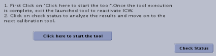
- After a task is completed, click Check Status in the right pane. Completed tasks turn blue; failed tasks turn red.
- ICW remains in installation mode until all tasks are successfully completed.
- Software version 29.0 introduces forced password changes on all user accounts to comply with minimum mandated security requirements for GE equipment.
- Password changes are mandated on two instances:
- When booting the software for the first time.
- When rebooting the system after completion of Install In Spec.
When running these tools within ICW, some of the finalization tasks such as Doing a TPS reset or Saving information will be automatically completed by ICW.
Procedure
- Use the following tables as a reference to identify what tasks are needed to complete each procedure within ICW.Note:
Relaunching a completed task in ICW displays a dialog showing prerequisite tasks. You may want to rerun the prerequisites listed before rerunning the selected task.
Figure 3. ICW alert dialog 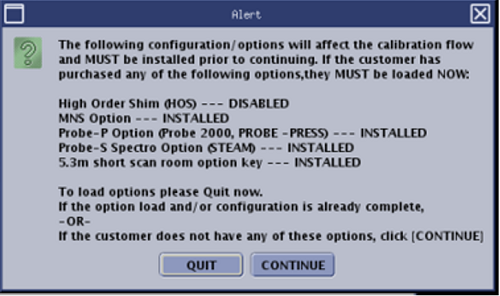
Procedure Tasks Personnel requirements Mechanical install hand-off to GE - - Power on sequencing 1 Power on sequencing 1. 1 person 30 minutes
ICC hose and valve check, and fill coolant ICC hose and valve inspection, coolant fill, and coolant leak check. 1 person 90 minutes
Power on sequencing 2 Power on sequencing 2. 1 person 30 minutes
Emergency stop and off check See Checking the Emergency Stop and Off functions. 1 person 45 minutes
Invoke ICW and check off - When you power up the host computer and see the login screen, click root login.
- Log in with the user name: root and password.Note: It is possible that the customer changed the default password. If you cannot log in, contact the customer for the correct password.
- Logging in as the root user automatically displays the Linux desktop and launches the Guided Install Starter window. Click No to ignore the Guided Install.
- Confirm that the service key is installed.
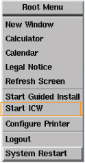
- Right-click on the Linux desktop to access the Root Menu and then select Start ICW.
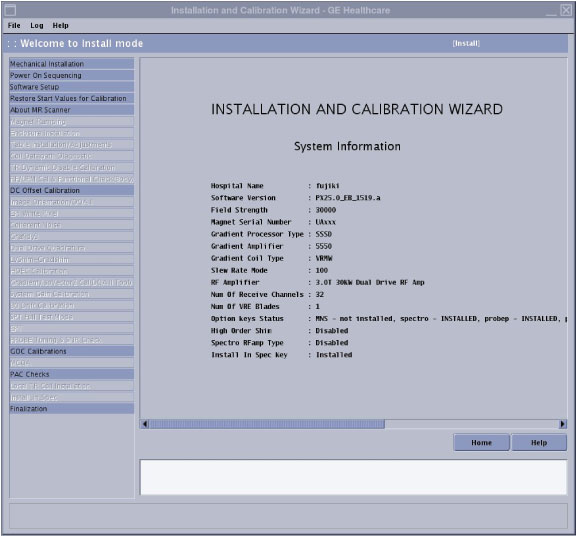
- ICW screen shows:
Mechanical Installation
Record the start and end dates.
Power on sequencing
Answer the following questions:- Have you filled chiller and lines with coolant?
- Is Magnet Monitor power connected to customer source?
- Have you completed system power on sequentially?
- Are the coolant leak checks done?
- Have you completed the E-Stop and E-Off functional checks?
Software setup
Answer the following questions:- Has the GOC come with software pre-loaded? (Yes/No)
If no, see Installing host system software (quick start).
- Does the system have the latest service pack software loaded? (Installing Service Packs)
- Have you loaded the customer Operator's Manual?
If not, see Installing operator documentation (online help).
- Have you restored the Start Values for Calibration? If not, see Restore Start Values for Calibration.
- Make sure the system parameters (hardware and software) are correct by viewing the About box. It is available from the Tools pull-down menu by selecting About MR Scanner.
- About MR scanner See Running the About MR Scanner tool.
Note: Make sure the system parameters and hardware configuration are correct for your system, and edit accordingly in Guided Install (see System and hardware configuration).1 person 5 minutes
Dock/Table Anchor Answer question related to two-part dock/table anchor. See Checking off ICW Dock/Table Anchor items.
- Enclosure removal for ramping and shimming Check that the covers are installed correctly and remove only the covers that are necessary for magnet ramping and shimming.
- Concealment kit covers
- Upper, front, and rear service access panels
- Front end bell covers
- Rear and inner bridge covers
For detailed instructions, see Removing and installing the magnet enclosure covers.
2 people 60 minutes
Removing the 1-piece bridge See Removing the 1-piece bridge. - Mapping fixture setup Refer to the Magnet and Cryogens subsystem manual for these tasks:- For UA magnets: Magnet and Cryogen Manual for Passively Shimmed Magnets (5495018)
- For AR magnets: Magnet and Cryogen Manual for 3.0T AR Series Magnets (5881576-8EN)
- Preparations of magnet ramp up - STET tool setup - Magnet ramping - Magnet ramp up cable disconnect - Magnet field drift rate check - Passive shimming - Check off magnet ramping in ICW Answer the following questions:- Are magnet preramping requirements done?
- Is the magnet rundown unit functional check done?
- Is magnet ramping done?
- Is passive shimming done on this magnet?
- Ground resistance checks (for patient table, ISC) See Measuring ground resistance. 1 person 60 minutes
Installing the 1-piece bridge Reinstall the 1-piece bridge and rear bridge covers after ramping and shimming. See Installing the 1-piece bridge. - Table adjustment See Doing ICW dockable table adjustments.
Note:- Do not install the cradle top cover for coil data path diagnostics.
- Power on the system to Applications mode and make sure the TPS reset is successful.
- Download and open the Alignment Data Sheet Macro (DOC2647017) from the online documentation library to use during table adjustments
- Do not electronically dock the dockable table until table alignment is complete. Damage to the ODU pins may occur.
2 people 4 hours and 20 minutes
Table functional check See Checking the patient table 1 person 60 minutes
Coil datapath diagnostic See ICW coil data path diagnostic. 1 person 2 hours
Set up the total digital imaging (TDI) posterior array (PA) See Setting up Total Digital Imaging (TDI) Posterior Array (PA) 1 person 60 minutes
Enclosure re-installation after ramping and shimming Reinstall the following covers, as applicable, after ramping and shimming: - Concealment kit covers
- Upper, front, and rear service access panels
- Front end bell covers
- Rear and inner bridge covers
For detailed instructions, see Removing and installing the magnet enclosure covers and Installing the cable concealment covers.
- Laser light check See Checking and aligning the laser light. 1 person 10 minutes
Body coil air flow check See Checking the body coil air flow. 1 person 1 hour and 15 minutes
TR dynamic disable See Calibrating transmit/receive dynamic disable. 1 person 3 minutes
Auto DQA calibration See Doing DQA calibration. 1 person 30 minutes (varies)
Gradient DC offset See DC offset adjustment. 1 person 5 minutes
Coherent noise check See Doing the ICW coherent noise check. 1 person 10 minutes
Grafidy See Calibrating grafidy. 1 person 2 hours
Auto DQA calibration See Doing DQA calibration. 1 person 40 minutes (varies)
LV shim (grad) See Running LVShim. - High order eddy current See Calibrating High Order Eddy Current (HOEC). 1 person 60 minutes
DD quad cal multi location See Dual drive quadrature tool. 1 person 45 minutes
B0 drift test Do Checking B0 Drift. If the test fails, see Calibrating B0 drift. 1 person 90 minutes
SPT See System Performance Test (SPT). - Probe calibration and SNR check (option) See PROBE/SV calibration and SNR tests. 1 person 1 hour and 30 minutes
GOC calibrations See Doing ICW GOC calibrations. 2 people 3 hours
MCQA Run MCQA for all applicable coils on site. See Coil information. Note: As a minimum requirement for ICW MCQA to pass the TDI PA, MCQA must pass.- PAC check See Checking off ICW PAC items. 1 person 45 minutes
Local TR coil installation (stability test for local TR coil) See Doing the local TR coil Stability test. 1 person 20 minutes
Finalization See ICW finalization. 1 person 45 minutes