- SIGNA™ Hero 3.0T Service Methods
- 5852800-8EN Revision 1.0
- 00000018WHA30DFB6GYZ
- id_20018145.0
- Nov 3, 2021 4:07:00 PM
Checking B0 Drift
Prerequisites
| Required persons | Preliminary requirements | Procedure | Finalization |
|---|---|---|---|
| 1 | Not applicable | 90 minutes | Not applicable |
| Item | Qty | Part# | Manufacturer |
|---|---|---|---|
| Body TLT Loader for 3.0T | 1 | 2360037 | - |
| Service Foam Positioner | 1 | 5554839 | - |
| Condition |
|---|
| All other applicable calibrations must be complete. |
| It is required to cool down the system without any scan for 2 hours before starting B0 drift test. Refer to the Cooling the system procedure. |
|
Before working in any GE Healthcare MR suite or performing any GE Healthcare service procedure, you must:
If you have any safety concerns at any time, do not begin work or immediately stop work and move to a safe location. Immediately contact your supervisor or site safety officer for instructions on how to proceed. |
About this task
Unwanted changes in the main magnetic field strength can occur when the spatially uniform field component is altered for a short term, during the process of scanning, or when the spatially uniform field component is permanently altered. This is known as short-term B0 drift.
This functional check confirms if the B0 drift values are within the system specification or not.
Procedure
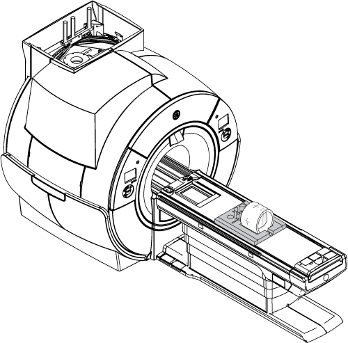
- Put the TLT phantom and sphere in the foam support on the flat table.
Position the phantom in the center of the cradle and center it on the Posterior Array (PA) coil. To achieve the best test measurement, the phantom must be located in the center (long direction) of the cradle.
Figure 1. TLT phantom and sphere on the table