Confirm internal power wiring to the Power Distribution Unit (PDU)
Procedure
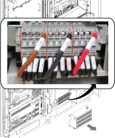
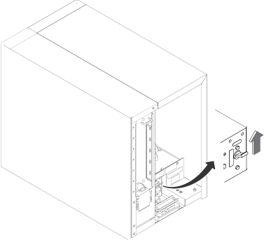
Remove the ISC PDU bottom cover.
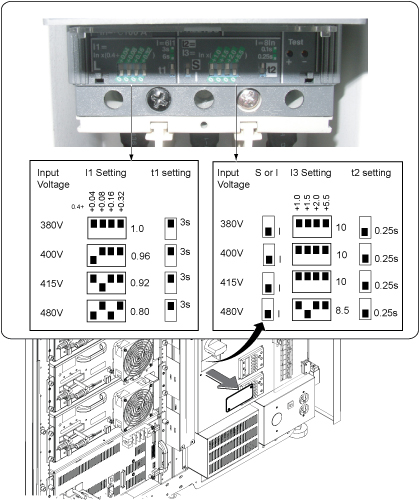
Confirm that the three Input Voltage Selection Terminal Blocks are wired in the correct configuration. If the power connections are not configured properly, ensure that the proper personnel correct the wiring.
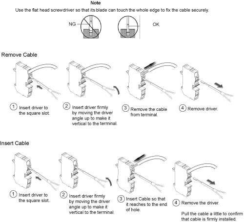
Figure 1. Input voltage selectionFigure 2. How to remove/install terminal cable
Notice
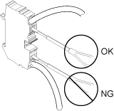
When removing or inserting cable, be careful not to insert the driver to the bottom terminal slot. It may cause the equipment damage if the cable connection of the terminal is loose.
Notice for removing and inserting cable
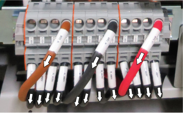
Pull all the cables at the terminal and confirm that the cables
are firmly connected to the terminal.
Figure 3. Cable connection check
Restore the ISC PDU bottom cover.
Topic ID: id_SL1816282-1178706
Confirm overload and short circuit trip settings for the PDU input circuit breaker
About this task
The overload and short circuit trip settings for the input circuit breaker must be set to the correct values corresponding to the input voltage.
Procedure
Remove the small cover plate under the main circuit breaker.
Lift open the transparent plastic cover on the lower portion of the circuit breaker to access the DIP switches controlling the circuit breaker.
Make sure the switches are configured correctly. The illustration below shows the position of the DIP switches for each input voltage.
Figure 4. Circuit breaker DIP switch settings
If the DIP switches are not configured correctly, correct the DIP switches settings.
Restore the small cover plate.
Topic ID: id_SL4802573-1178706
Check gradient cable connection at gradient filter
Procedure
Check the gradient cable connections at gradient filter at penetration panel of ISC to make sure there are no shorts between two axis or load shorts to ground.
Note: Complete this section BEFORE applying power to the system.
Make sure the following checks between points are low resistance (< 5 ohms) with a DVM in the following table.
Table 2. Gradient coil load check — ensure same coil
From
To
Expected value
X-Axis +
X-Axis –
< 5 ohms
Y-Axis +
Y-Axis –
< 5 ohms
Z-Axis +
Z-Axis –
< 5 ohms
Make sure the following checks between points are open (> 10 k ohms) with a DVM in the following table.
Table 3. Gradient coil load check — no shorts
From
To
Expected Value
X-Axis +
Y-Axis +
> 10 k ohms
X-Axis +
Z-Axis +
> 10 k ohms
Y-Axis +
Z-Axis +
> 10 k ohms
X-Axis +
Ground
> 10 k ohms
Y-Axis +
Ground
> 10 k ohms
Z-Axis +
Ground
> 10 k ohms
If any of the Table 1 and Table 2 checks fail, review the installation
instructions for gradient cable connections between the magnet and
the ISC prior to applying power to the system.
Note: This check does not ensure X, Y and Z gradient load coils are connected to the corresponding gradient amplifier.
Topic ID: id_SL12731103-1178706
System power on
Procedure
Make sure all circuit breakers on the front of the ISC cabinet PDU are in the off position.
Set the GOC PDU breaker to on position.
Figure 5. GOC PDU breaker
Notify field service and other installation personnel who are
working at the installation site that the LOTO will be removed so
the MDP or Facility PDU power can be turned on.
Restore power of ISC PDU at MDP or facility PDU.
Switch on the ISC PDU main breaker.
Switch the sub breakers to on according to the following order.
Cabinet sub breaker on
Push EMO Reset button
System cooling sub breaker on
HOST sub breaker on
ICE/ICN sub breaker on
Note: Host and ICE/ICN sub breaker must be on when turning on the GCU power in ICC.