Installs the dockable table motor onto the motor and ElectroMagnetic (EM) clutch assembly.
Prerequisites
Personnel requirements
Required persons
Preliminary requirements
Procedure
Finalization
1
-
5 minutes
-
Tools and test equipment
Item
Quantity
Part number
Manufacturer
Nonmagnetic Titanium Service Tool Kit, Small Set
1
5113258
-
Consumables
Item
Quantity
Part number
Manufacturer
Loctite #243
As needed
5415261-3
-
Required conditions
The pulley and mounting plate are installed on the motor.
Procedure
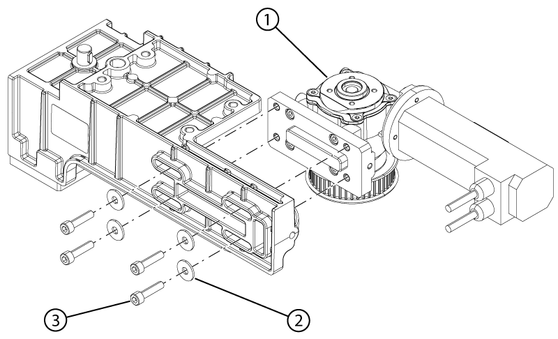
Install the motor onto the motor and clutch assembly.
Figure 1. Motor hardware
1
Motor
2
Washer
3
Screw
Install the four screws and four washers securing the motor to the motor and clutch assembly. Do not tighten the screws.
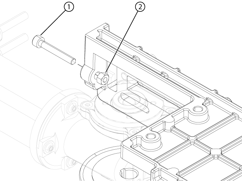
Install the belt tension screw and nut.
Figure 2. Motor belt tension hardware
1
Belt tension screw
2
Belt tension nut
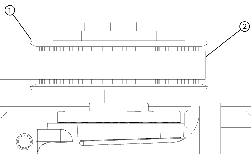
Install the new belt on the EM clutch and motor pullies.
Note: Make sure the belt is at the center of the pullies.
Figure 3. Belt centered on pulley
1
Pulley
2
Belt
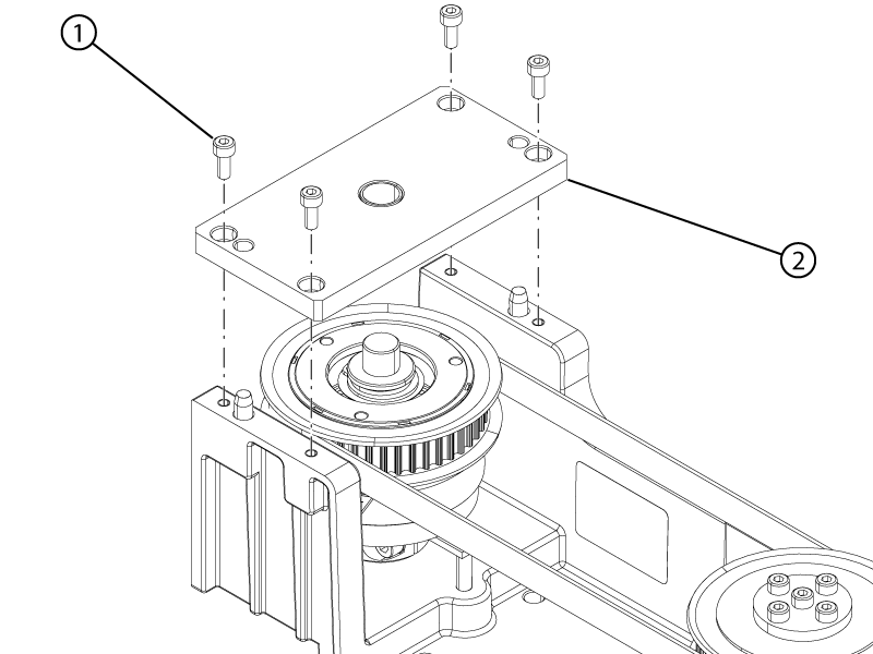
Install the clutch cover plate onto the motor and clutch assembly.
Note: Align the guide pins on the motor and clutch assembly housing with the alignment holes on the clutch cover plate.
Figure 4. EM clutch cover
1
EM cover screw
2
EM cover
Apply Loctite #243 to the four cover screws.
Install the four screws securing the clutch cover to the motor and clutch assembly.
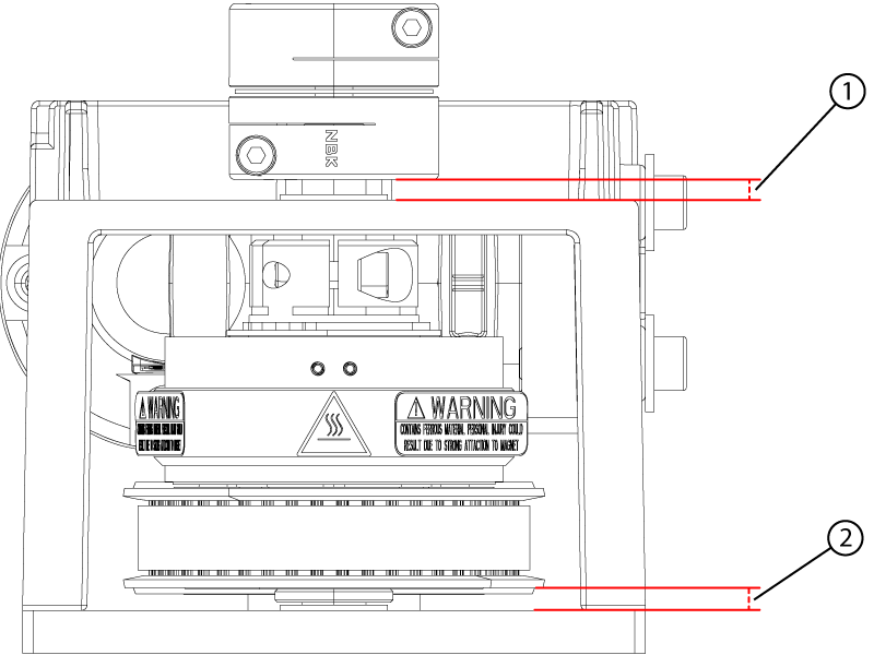
Make sure the gap between the EM clutch and the motor and clutch assembly housing is 4.2 ± 0.5 mm.
Note: The gap should be withing specification when the clutch is pushed down completely.
Figure 5. Motor coupler and electromagnetic clutch gaps
1
Motor coupler gap
2
EM clutch gap
Make sure the gap between the motor coupler and the motor and clutch assembly housing is 3.8 ± 0.5 mm. Loosen the coupler bottom screw and adjust the position of the coupler on the clutch shaft if required and then retighten the screw.
Make sure the belt is still centered on the pulleys.
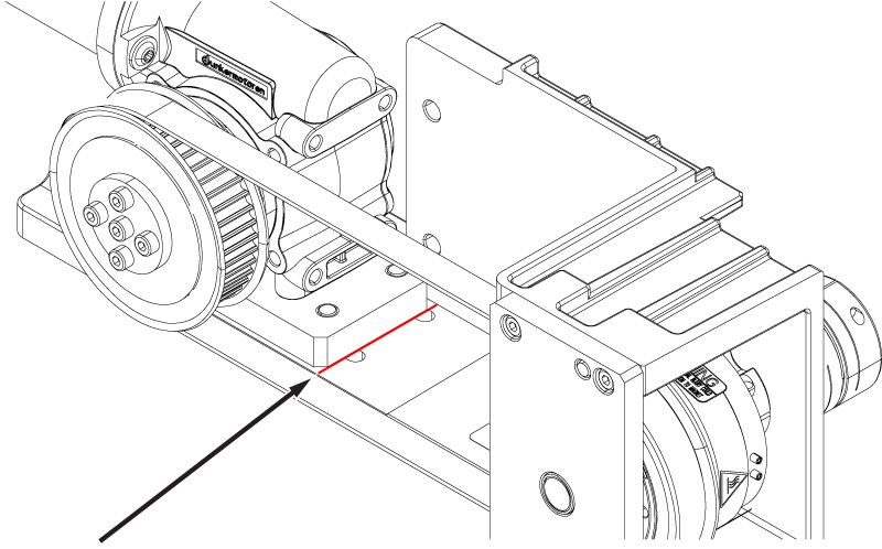
Align the edge of the motor with the mark on the motor housing.
Note: Move the motor close to the mark by hand, then use the belt tension screw to complete the alignment.
Figure 6. Motor position mark
Tighten the four screws securing the motor to the motor and clutch assembly.
Note: Make sure the motor does not move from its aligned position while tightening the screws.