- SIGNA MR355 / SIGNA MR360
- Service Manual
- 5856356-3EN Revision 5.0
- Basic Service Documentation. Copyright General Electric Company.
- 00000018WIA30E82B10GYZ
- id_20068111.18
- May 31, 2020 11:23:44 PM
Installing the Global Operator Cabinet (GOC) Power Distribution Unit (PDU)
Install a new or replacement PDU in the GOC.
Prerequisites
| Personnel requirements | |||
|---|---|---|---|
| Required persons | Preliminary requirements | Procedure | Finalization |
| 1 | - | 25 minutes | - |
| Tools and test equipment | |||
|---|---|---|---|
| Item | Quantity | Part number | Manufacturer |
| Screwdriver | 1 | - | - |
| Replacement parts | |||
|---|---|---|---|
| Item | Quantity | Part number | Manufacturer |
| GOC Power Distribution Unit with 1-Wire | 1 | 5502029-2 | - |
Procedure
- Insert the PDU into the slot in the GOC.
Figure 1. Inserting the GOC PDU 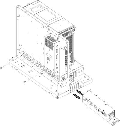
- Position the GOC chassis facing plate on the back of the GOC.
Figure 2. GOC chassis facing plate 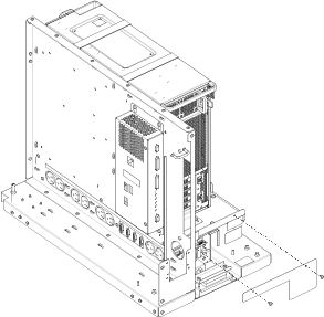
- Reconnect the PDU cables.
Figure 3. GOC PDU cables 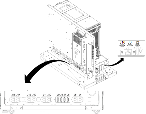
Item Description J1 Cabinet power supply J2 Not used. Do not use this outlet for servicing.
J3 Not used. Do not use this outlet for servicing.
J4 LCD Monitor Power
J5 Host computer power J6 Not used. Do not use this outlet for servicing.
J7 Not used. Do not use this outlet for servicing.
J8 Not used. Do not use this outlet for servicing.
J9 Not used. Do not use this outlet for servicing.
J10 Not used. Do not use this outlet for servicing.
J11 Not used. Do not use this outlet for servicing.
J12 Not used. Do not use this outlet for servicing.
J13 Not used. Do not use this outlet for servicing. J14 Not used. Do not use this outlet for servicing. J15 Not used. Do not use this outlet for servicing. J16 GOCAA DC power - Set the GOC PDU breaker CB1 switch to the on position.
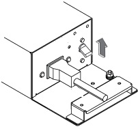
Figure 4. GOC PDU breaker switch