Positions the laser levels for dockable table adjustments.
Prerequisites
Personnel requirements
Required persons
Preliminary requirements
Procedure
Finalization
1
-
15 minutes
-
Tools and test equipment
Item
Quantity
Part number
Manufacturer
Laser Level PLS 180R Z
2
5831466
-
Tripod, Vanguard Alta Pro 263AB 100
2
5829559
-
150 mm Plastic Dial Caliper with Metric Readout
1
5916010
-
Procedure
Assemble both alignment lasers on tripods with the adjusters.
Place the lasers at the front of the scan room, at least two feet from the handle end of the table with the lasers pointing down the bore of the magnet.
Important: The tripods are ferrous. Keep the tripods outside of the 200 G line.
Turn on the first laser with horizontal and vertical beams.
Note: Make sure the lasers are unlocked.
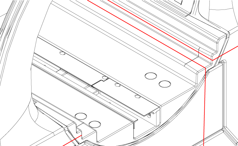
Align the first laser with the lasers centered on the horizontal and vertical surfaces of the bridge as shown.
Note: Lower the table as required for laser alignment.
Figure 1. Lasers on bridge surfaces
Turn on the second laser with only a vertical beam.
Align the second laser similarly to the first laser on the opposite side of the system.
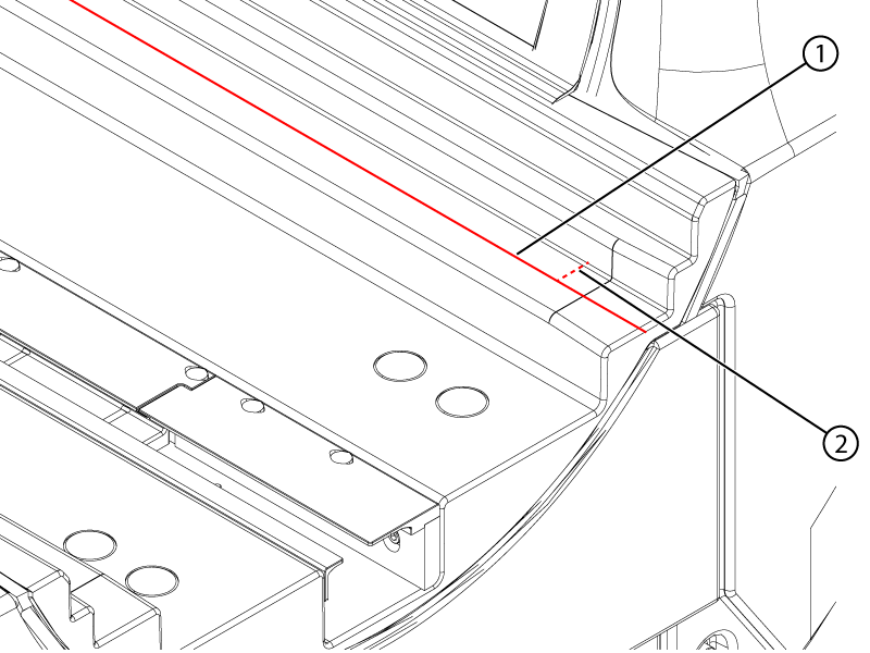
Measure the distance from the bridge vertical surface to the laser at the front and rear of the magnet bore.
Note: Measure approximately 60 mm from the edge of the bridge to avoid the profile change.
Figure 2. Horizontal measurement
1
Laser
2
Horizontal measurement
Enter the measurements into the spreadsheet.
Adjust the angle of the laser to align the measurements.
Note: Keep the lasers approximately parallel to the bridge so that the vertical distance measurements between the laser and the bridge horizontal surface at the front and rear of the bridge are within 1 mm of each other.
Repeat Step 7 to Step 9 until the measurement difference on each laser is within 1 mm.