Install the Integrated Control Engine (ICE) fan assembly in the System Cabinet.
Prerequisites
| Personnel requirements |
|---|
| Required persons | Preliminary requirements | Procedure | Finalization |
|---|
| 1 | - | 5 to 10 minutes | - |
| Tools and test equipment |
|---|
| Item | Quantity | Part number | Manufacturer |
|---|
| Nonmagnetic Titanium Service Tool Kit, Small Set | 1 Kit | 5113258 | - |
| Nonmagnetic Titanium Service Tool Kit, Large Set | 5112581 | - |
| Replacement parts |
|---|
| Item | Quantity | Part number | Manufacturer |
|---|
|
ICE Fan Assembly
pICE fan | 2 |
Refer to FRU Manual5485930 | - |
Procedure
- Do the following steps to install a fan in the back of the ICE.
- Connect the fan cable to the power cable in the hole beside the fan slot.
Note: Be careful that the power cable does not fall into the hole.
Figure 1. Hole for power cable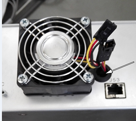
- Tighten four screws to secure the fan to the ICE.
Figure 2. Installing the fan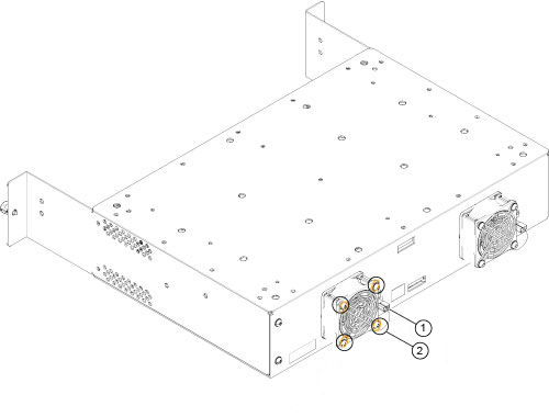
| 1 | Connect the fan cable to the power cable |
| 2 | Tighten four screws |
- Restore the clamps and tie wraps on the top of the ICE and connect the cables to the rear panel as shown below.
Figure 3. Clamps, tie wraps, and rear connections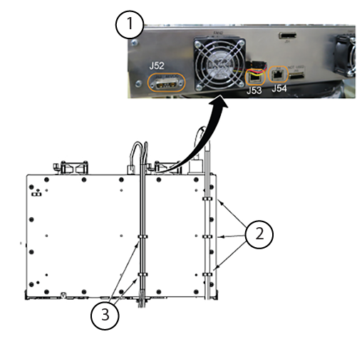
| 1 | ICE rear panel connections |
| 2 | ICE top view, tie wraps for power cable |
| 3 | ICE top view, tie wraps for Ethernet cables |
- Restore the ICE by reverse order.
Note: When you move the power plug in and out, keep it clear of the flap on the front of the Ethernet bracket.
Figure 4. Power plug near Ethernet bracket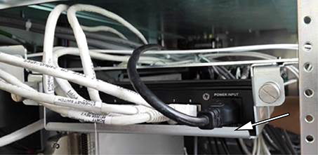
Note: When you move the ICE in and out, keep it clear of the Ethernet assembly.
Figure 5. ICE near Ethernet assembly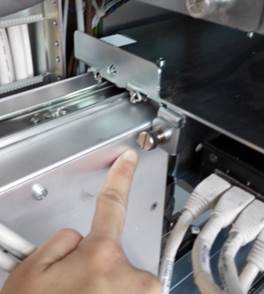
Note: When you push the ICE into the ISC/PGR, be careful not to pinch the cables next to the chassis.
Figure 6. Cables next to the chassis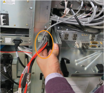
| Notice |
|---|
 | Component damage risk Applying too much force when pins are not properly aligned to the corresponding socket will bend the pins and can break the connector or cable. J28 of the ICE front panel is a Twin BNC connector for the local oscillator (LO) cable. Align the pins and keys properly before connecting them.
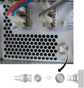 |
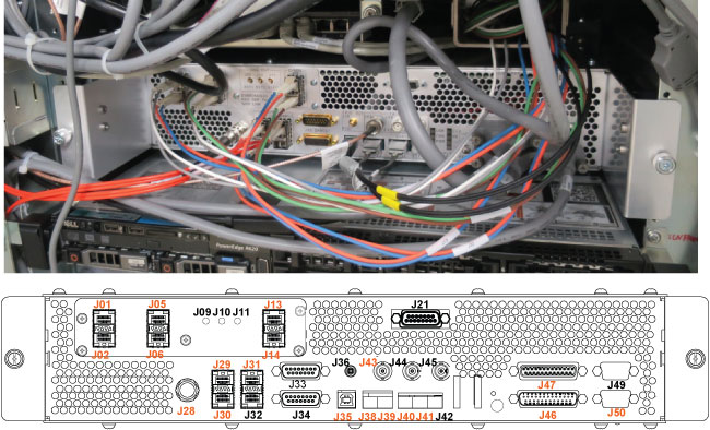
Note: Restore the cables as shown below. J numbers in orange need to be reconnected.
Figure 7. Cable restoration