Dangerous and or fatal voltages are present in the energized cabinet.
Follow LOTO steps as given in first section of this document to disable and verify safe voltage levels.
About this task
This procedure describes the replacement procedure for two USB extender cables (ISC internal cable(ICE to ISC top) and system cable (GOC to ISC)).
Note: It’s important to replace both cables. Especially root part number of both cable should be the same after the replacement. (e,g. 5725077 and 5725077-2)
Procedure
Warning
ELECTROCUTION HAZARD!
Cabinet top area that includes power cable wiring Will be accessed in this procedure.
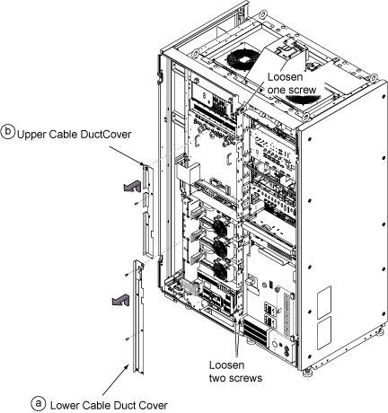
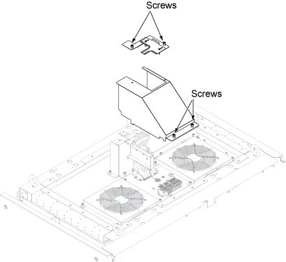
Loosen two bottom screws, remove two screws, and lift up Lower Cable Duct Cover to remove it.
Loosen one top screw, remove one screw, and lift up Upper Cable Duct Cover to remove it.
Figure 1. Remove cable duct covers
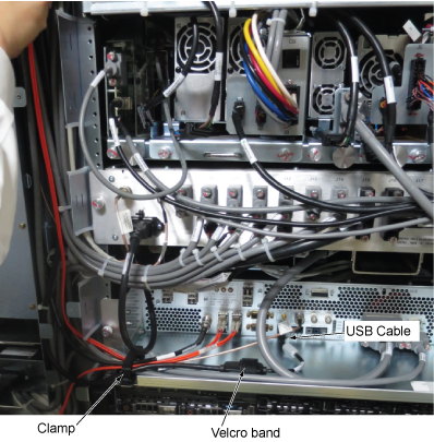
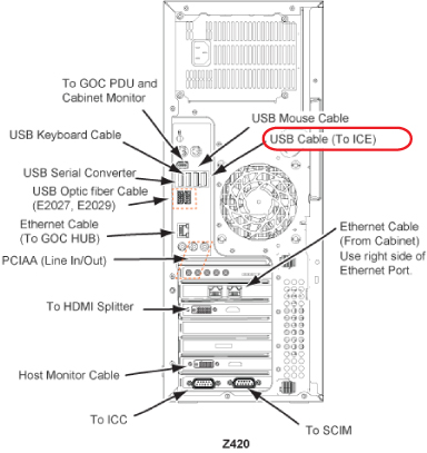
Open clamp and velcro band. Then, disconnect USB cable from ICE.
Figure 2. USB cable at ICE
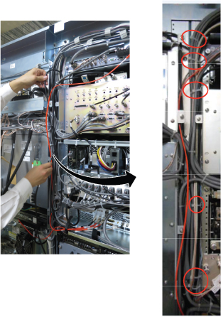
Cut tie wraps that is connecting the USB cables in the cable duct.
Figure 3. Cut tie wraps
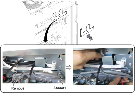
Remove two screws and loosen one screw. Then, slide the plate to the left and remove it.
Figure 4. Plate removal
Remove ISC connector cover by removing 4 screws.
Figure 5. ISC Top Connector cover
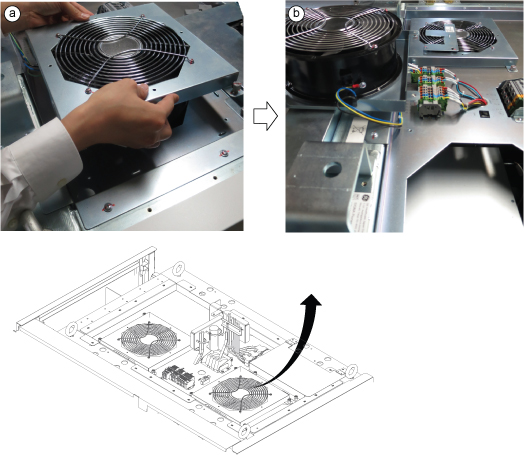
Perform the following steps.
Loosen 4 screws from right Top FAN and remove it.
Flip and put it on the top of the Cabinet.
Figure 6. Disconnect power
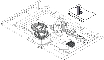
Loosen two screws and remove top plate cover.
Figure 7. Top plate cover
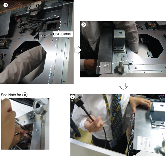
Remove USB Cable to the front of the cabinet per following steps.
Access USB Cable from the opening of Fan.
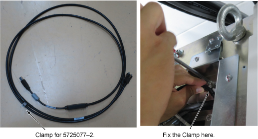
Note: For USB Cable (5725077–2), remove a screw which is connecting the cable clamp to the chassis.
Gradually pull the cable to the front.
Remove the cable to the front.
Figure 8. USB Cable removal to the front
Restore new USB cable in reverse order of the removal for ISC.
Note: For USB Cable (5725077–2), fix the cable clamp to the chassis with a screw.
Figure 9. USB Cable Clamp
Route the USB extender system Cable (E3037) from GOC to ISC and connect it to both Z420 and ISC top cable.
Note: For time saving, leave the old USB extender system cable as routed on the cable tray. If old cable is left on the tray, bent each ends of the cable, secure them with tie wraps, and put tapes (e.g. packing tape) on each ends with hand writing note as "Don’t use".