
- SIGNA™ Hero 3.0T Service Methods
- 5852800-8EN Revision 1.0
- 00000018WIA306EEE20GYZ
- id_131064333.3
- Sep 2, 2021 11:21:49 AM
Body Coil Isolation
Prerequisites
| Required persons | Preliminary requirements | Procedure | Finalization |
|---|---|---|---|
| 1 | 0 minutes | 30 minutes | 0 minutes |
| Item | Quantity | Effectivity | Part number | Manufacturer |
|---|---|---|---|---|
| Non Magnetic Tool including Allen Wrench to adjust body coil RL position | 1 | - | - | - |
| Step Gauge (Placed at rear mounting bracket) | 1 | - |
5492609 | - |
| ||||
| Condition | Reference | Effectivity |
|---|---|---|
|
LOTO FOR ISC is performed | - | - |
| - | - | |
| - | - |
About this task
In this procedure, Body Coil position will be centered to the inner Gradient Coil.
Measurement will be performed at 4 locations for both Front and Rear.
Since there are former supports at 0 degree, 90 degree, and 270 degree positions and it prevents the correct measurement, the gauge will be placed next to the screws near former support (Position A, C, and D in illustration below). At 180 degree (Position B), there is no former support and measurement will be done at 180 degree position.
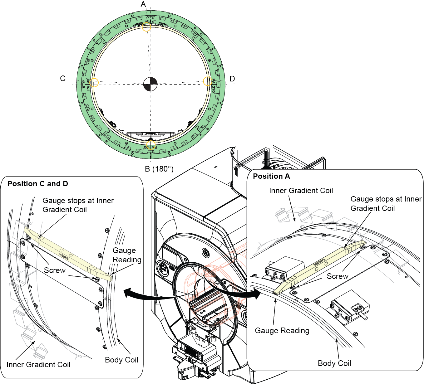
| ID | Position |
| A | Top Measurement Position |
| B | Bottom Measurement Position |
| C | Left Measurement Position |
| D | Right Measurement Position |
New type of Body Coil support is introduced in Q3, 2016. Two types of body coil support are shown in this procedure.
Body Coil AP Alignment
Procedure
- If not done, disconnect the two (2) cooling air ducts at the
rear end of the body coil.
Figure 2. Cooling air ducts - Find Step Gauge which is placed at rear mounting bracket and
remove it.
Figure 3. Step Gauge Location (Rear Magnet) 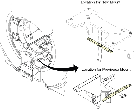
- Confirm that screws and nuts shown in the following illustration
are tightened for Front side and Rear side.
Figure 4. Confirmation 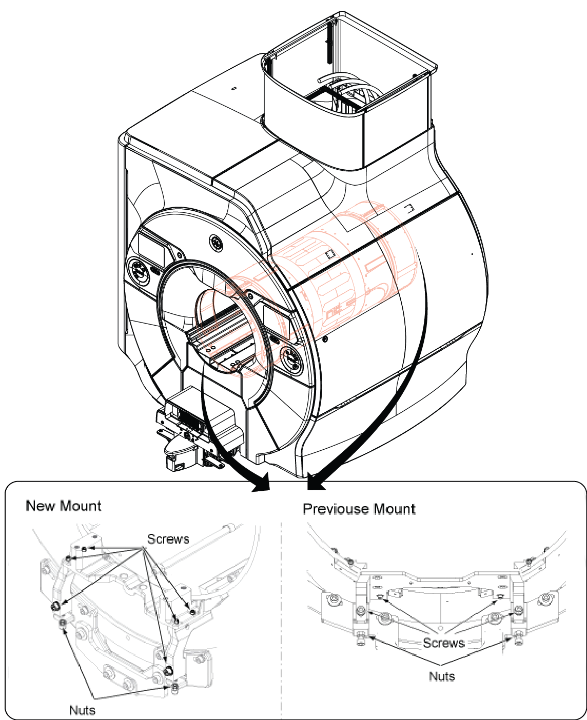
- At front end, check the gaps between Body Coil and Inner Gradient
Coil at 2 vertical measurement locations (A and B) using Step Gauge.
Spec: Differential of Gap (A) and Gap (B) ≤ 0.5mm (Identical or no more than 1 Adjacent Step).
Options of 1 Adjacent Step: a) 9.5 & 10; b) 10 & 10.5; c) 10.5 & 11; d) 11 & 11.5, e) 11.5 & 12
Figure 5. Step Gauge 
Table 6. Gap Option Matrix If gap at A = Then gap at B must = 9.5 9.5 or 10 10 9.5 or 10 or 10.5 10.5 10 or 10.5 or 11 11 10.5 or 11 or 11.5 11.5 11 or 11.5 or 12 12 11.5 or 12 Note:There are several notes when measuring the gap.
-
Since there is a former support at 0 degree position, place the gauge next to the screw shown in illustration below (Position A).
-
Push fully to the inner bore side so that the gauge stops at inner gradient coil.
Check that the gauge is not stopped at the level difference between bore light panel and hard body coil.
-
Read the gauge at the edge of body coil.
-
Insert side A first (Figure 5). If the gauge stops at 10.5 position, insert side B. If the gauge stops before 11 position line, the gap is 10.5.
Figure 6. GAP Check 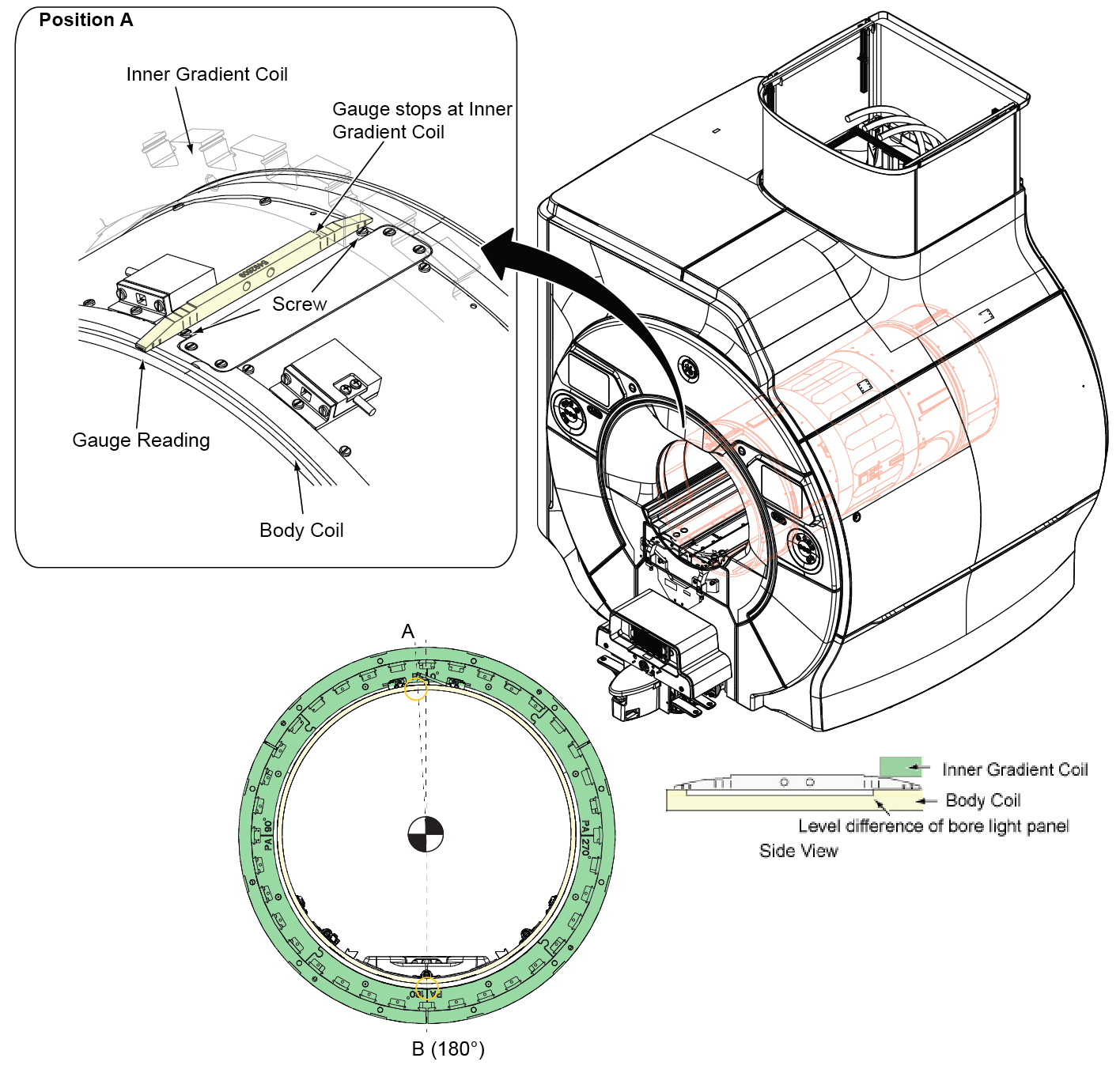
-
- If the gaps does not satisfy the specification in step 4, adjust
AP position using RF Body Coil support to meet the specification.
Figure 7. Adjustment of RF Body Coil support (AP position) 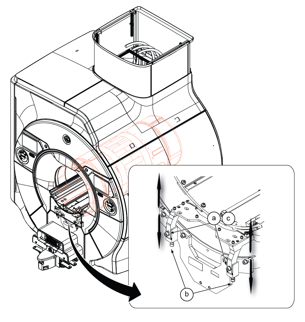
Body Coil RL Alignment
Procedure
- Confirm that screws and nuts shown in the following illustration
are tightened for Front side and Rear side.
Figure 8. Confirmation - At front end, check the gaps between Body Coil and Inner Gradient
Coil at 2 horizontal measurement locations using Step Gauge. Slide
the Step Gauge between the hard body coil outside diameter and the
hard gradient coil inside diameter until it will not slide any further.
The value on the last step to slide between the body coil and the
gradient coil indicates the gap. The step gauge is marked in ‘mm’.
Spec: Differential of Gap (C) and (D) ≤ 0.5mm (Identical or no more than 1 Adjacent Step).
Options of 1 Adjacent Step: a) 9 & 9.5; b) 9.5 & 10; c) 10 & 10.5; d) 10.5 & 11, e) 11 & 11.5
Figure 9. Step Gauge Table 7. Gap Option Matrix If gap at C = Then gap at D must = 9.5 9.5 or 10 10 9.5 or 10 or 10.5 10.5 10 or 10.5 or 11 11 10.5 or 11 or 11.5 11.5 11 or 11.5 or 12 12 11.5 or 12 Note:There are several notes when measuring the gap.
-
Since there is a former support at 90 degree and 270 degree position, place the gauge next to the screw shown in illustration below (Position C and D).
-
Push fully to the inner bore side so that the gauge stops at inner gradient coil.
Check that the gauge is not stopped at the level difference between bore light panel and hard body coil.
-
Read the gauge at the edge of body coil.
-
Insert side A first (Figure 9). If the gauge stops at 10.5 position, insert side B. If the gauge stops before 11 position line, the gap is 10.5.
Figure 10. GAP Check 2 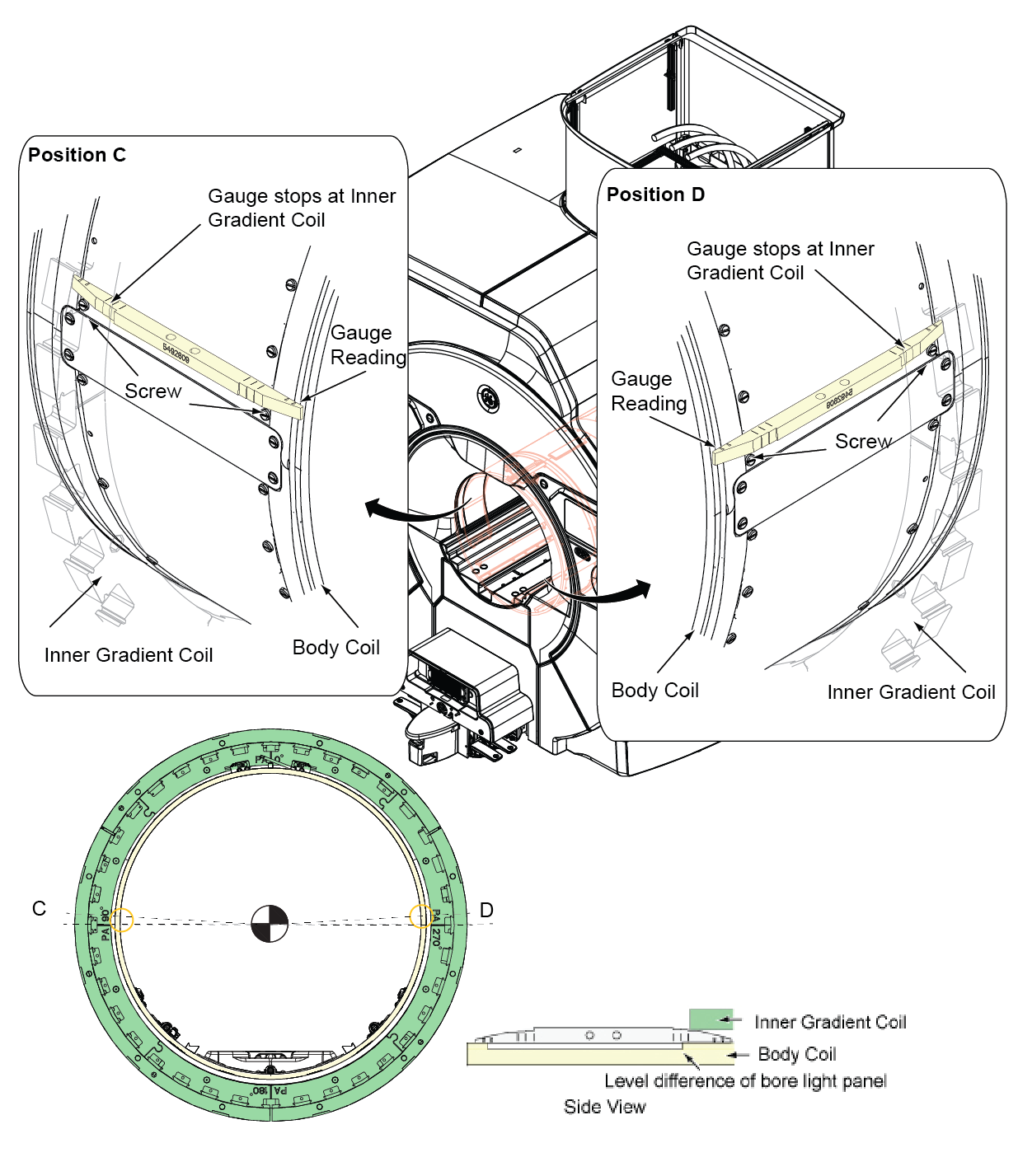
-
- If the gaps does not satisfy the specification in step 1, adjust
RL position using RF Body Coil support to meet the specification.
Figure 11. Adjustment of RF Body Coil support (RL position) 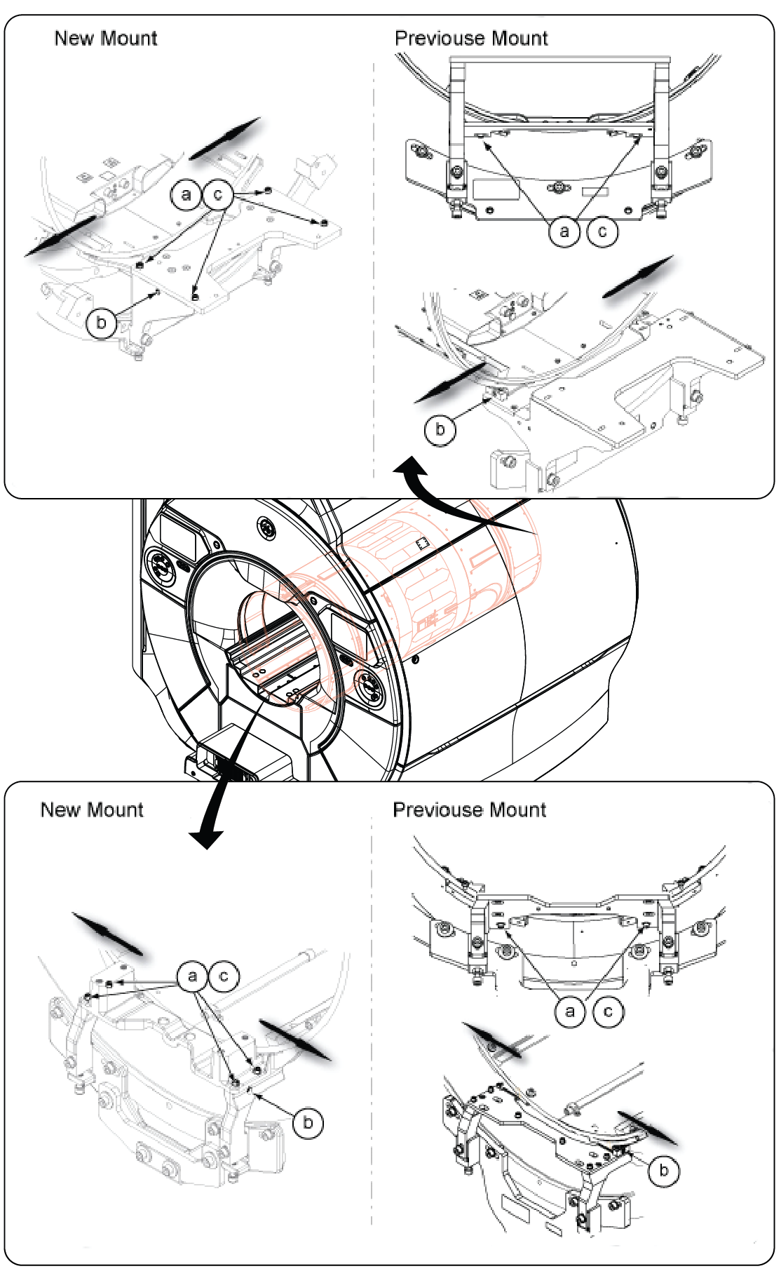
Final Check
Procedure
- After re-tightening any loosened nuts, check RL position and AP position of Front End and Rear End again per Body Coil AP Alignment and Body Coil RL Alignment and adjust the position if necessary until the specifications are satisfied.
- Restore Step Gauge at rear mounting bracket.
- If you are doing RF Body Coil Replacement Procedure, return to the original procedure. Changing RF Body coil isolation/alignment will affect coil tuning
Finalization
Finalization
No finalization steps.