
- SIGNA™ Hero 3.0T Service Methods
- 5852800-8EN Revision 1.0
- 00000018WIA30BEC230GYZ
- id_156673411.23
- Jan 26, 2022 3:37:20 PM
VRMw cable busbar replacement
Prerequisites
| Personnel requirements | |||
|---|---|---|---|
| Required persons | Preliminary requirements | Procedure | Finalization |
| 2 | 3 hours | 5 hours | 3 to 4 hours |
| Tools and test equipment | |||
|---|---|---|---|
| Item | Quantity | Part number | Manufacturer |
| Pair: Nonferrous Safety Shoes | 1 for each person | - | - |
| Safety Glasses | 1 for each person | - | - |
| Pair: Cut-Resistant Gloves | 1 for each person | - | - |
| Arc Flash PPE | 1 | - | - |
| Nonmagnetic Titanium Service Tool Kit, Large Set | 1 | 5112581 | - |
| Torque Wrench, 8-50 N m Adjustable, non-magnetic | 1 |
5534134 or 5534134-2 | - |
| Consumables | |||
|---|---|---|---|
| Item | Quantity | Part number | Manufacturer |
| Loctite #243 (check expiration date) | 1 | 5415261-3 | - |
| Loctite 271 (check expiration date) | 1 | 46-170684P2 | - |
| Alcohol Wipes | As needed | - | - |
| Black Sharpie Pen | 1 | - | - |
| Replacement parts | |||
|---|---|---|---|
| Item | Quantity | Part number | Manufacturer |
| XZ VRMw Busbar | 1 |
Refer to FRU Manual | - |
| Y VRMw Busbar | 1 |
Refer to FRU Manual | - |
| Required conditions |
|---|
|
Remove the rear endbell. |
| ||||||||
About this task
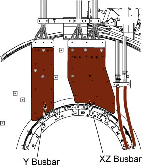
This procedure describes the replacement or installation process of the VRMw Cable Busbar.
There are two separate busbars; XZ busbar assembly and the Y busbar assembly. Typically, only one busbar will be replaced at one time.
Lockout/Tagout
About this task
Follow all safety lockout/tagout procedures:
Procedure
Y busbar removal
Procedure
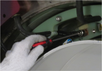
- Remove the cable clamp. Note: DO NOT remove the clamps on the busbar leads.
Figure 2. Cable clamps 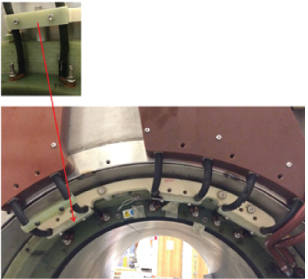
- At the service end, remove the safety covers from the end of the Y busbar cable connections.
Figure 3. Safety cover 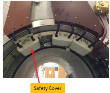
Remove two M10 brass nuts and Nord-lock washers that secure the busbar lugs to the coil. Slide the busbar terminal lugs off of the studs at the coil.Notice  Note:
Note:Never use the nonmagnetic torque wrench to loosen connections, the torque wrench has a range of 10 - 50 N*m ( 8 – 35lbf*ft), removing Nord-Lock© or Spiralock© threads may exceed the limit of this wrench and destroy the ratchet components.
Figure 4. Removing brass nuts and Nord-Lock washers - coil end 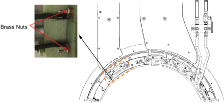
- At the top of the busbar, remove the four M10 brass nuts and Nord-lock washers that secure the busbar lugs to the magnet. Slide the busbar terminal lugs off of the studs on the busbar.
Figure 5. Disconnecting gradient power cables 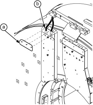
- Remove the ten brass nuts and G10 washers that secure the Y busbar to the magnet.
Figure 6. Y busbar mounting points 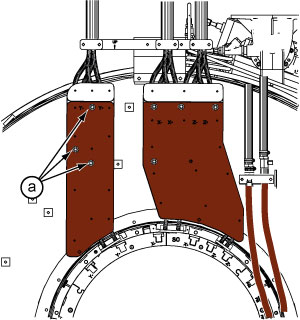
Y busbar installation
Procedure
- Make sure a the rubber bushings (smaller side faces out) are on each mounting stud. Make sure the coil-side mating surface is clean and void of epoxy.
Figure 7. Rubber bushing 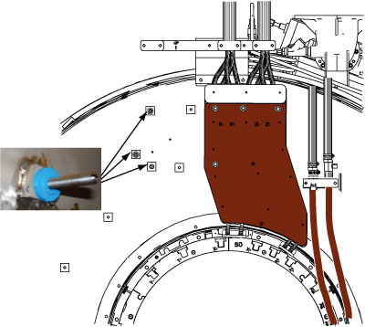
- Starting at the top and moving clockwise between mounting studs, hand-tighten each nut evenly. Again moving clockwise between studs, tighten one full turn (1/2 turn at a time). Conclude when 2-3 threads are showing above each nut.
Figure 8. Location of brass nuts - Y busbar Notice Note: Observe the following:Put a new Nord-Lock washer over the stud. Put two drops of Loctite 243 on the exposed thread.-
Always use the new Nord-lock washers that come with the FRU package. DO NOT reuse the old Nord-lock washers.
-
Nord-lock washers consist of two pieces, which are generally glued together. Always use a complete set with two pieces joined together in correct orientation. DO NOT use a separated single piece. If the Nord-Lock washers are separated, or the nuts are untightened, discard the washers and replace them with new Nord-Lock washers only. If new Nord-Lock washers are not available, contact the online center for further instructions.
Figure 9. Nord-Lock washers 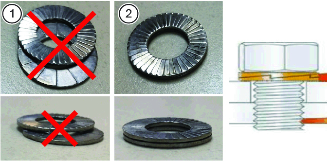
1 Wrong (do not use separated washers) 2 Correct
Do not get Loctite on the Nord-Lock washer. Hand-tighten the nut.
Discard the old washers.
Figure 10. Loctite on stud 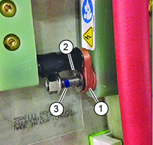
1 Busbar terminal lug 2 Loctite on stud 3 Nord-Lock washer (installed after lug) Figure 11. Tightening brass nuts -
DANGER Notice Notice
Set the torque wrench to 25 ft-lbs or 33.9 Nm. Install 15 mm socket on the extension.Notice  Note: Make sure that the arrow on the torque wrench is visible. If the arrow is not visible, the torque wrench will not “click” when the proper torque is reached.
Figure 12. Arrow on nonmagnetic torque wrench 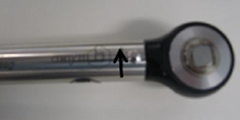
- Using a Sharpie pen, place a line from the base of the stud to the nut.
Figure 13. Stud and nut marked to show torque position 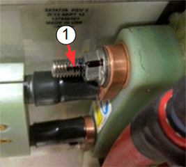
1 Black line on nut and stud to show torque position. - Restore and secure the safety cover.
Figure 14. Safety cover - Install the cable clamp.
Figure 15. Cable clamp - At the top of the busbar (after applying system cables), install Nord-lock washers (new), then brass nuts, onto the studs of the busbar. Hand-tighten brass nuts plus a half turn with a 17 mm non-magnetic wrench. Do not overtighten nuts. At the top of the busbar, install plastic cover with two screws to the busbar.
Figure 16. Installation sequence of terminal Note: Observe the following:-
Proper torque to the nuts holding the busbar lugs is critical to the long-term stability of the gradient subsystem.
-
XZ busbar removal
Procedure
- Remove the cable clamps .
Figure 17. Cable clamps 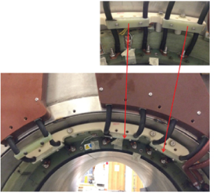
- Remove eight M4 x 10 mm screws and two Safety Cover Tops (clear plastic) from the busbar.
Figure 18. XZ busbar safety covers 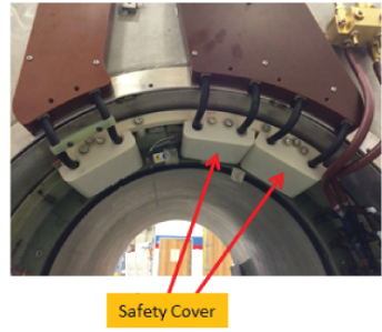
Remove four M10 brass nuts and Nord-lock washers that secure the busbar lugs to the gradient coil.Notice  Note:
Note:Never use the nonmagnetic torque wrench to loosen connections, the torque wrench has a range of 10 - 50 N*m ( 8 – 35lbf*ft), removing Nord-Lock© or Spiralock© threads may exceed the limit of this wrench and destroy the ratchet components.
Figure 19. Removing brass nuts and Nord-Lock washers - coil end 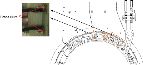
- At the top of the busbar, remove eight M10 brass nuts and Nord-lock washers that secure the busbar lugs to the system. Slide the busbar terminal lugs from the studs on the busbar.
Figure 20. Disconnecting gradient power cables - magnet end 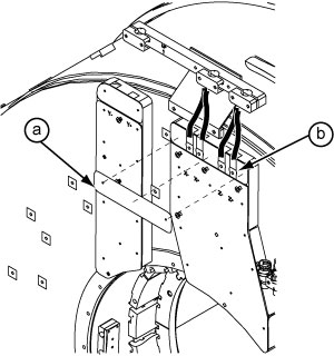
- Remove the six brass nuts and washers that secure the XZ busbar to the magnet.
Figure 21. XZ busbar mounting points 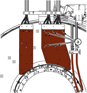
XZ busbar installation
Procedure
- Make sure a the rubber bushings (smaller side faces out) are on each mounting stud. Make sure the coil-side mating surface is clean and void of epoxy.
Figure 22. Rubber bushing 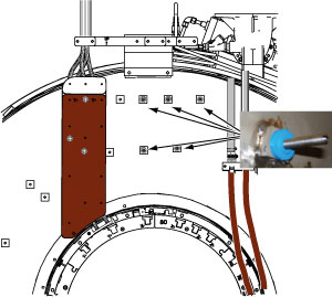
- Starting at the top and moving clockwise between mounting studs, hand-tighten each nut evenly. Again moving clockwise between studs, tighten one full turn (1/2 turn at a time). Conclude when 2-3 threads are showing above each nut.
Figure 23. Location of brass nuts - XZ busbar Notice Note: Observe the following:Place a new Nord-Lock washer over the stud. Put two drops of Loctite 243 on the exposed thread.- Always use the new Nord-lock washers that come with the FRU package. DO NOT reuse the old Nord-lock washers.
- Nord-lock washers consist of two pieces, which are generally glued together. Always use a complete set with two pieces joined together in correct orientation. DO NOT use a separated single piece.
Figure 24. Nord-Lock washers 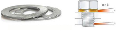
Do not get Loctite on the Nord-Lock washer. Hand-tighten the nut.
Discard the old washers.
Figure 25. Loctite on stud 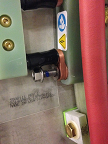
Figure 26. Tightening brass nuts DANGER Notice Notice
Set the torque wrench to 25 ft-lbs or 33.9 Nm. Install 15 mm socket on the extension.Notice Note: Make sure that the arrow on the torque wrench is visible. If the arrow is not visible, the torque wrench will not “click” when the proper torque is reached.Figure 27. Arrow on nonmagnetic torque wrench - Using a Sharpie pen, place a line from the base of the stud to the nut.
Figure 28. Stud and nut marked to show torque position 1 Black line on nut and stud to show torque position - Restore and secure the safety cover.
Figure 29. Safety cover - Install the cable clamps.
Figure 30. Cable clamps - At the top of the busbar, place the terminal lugs of the gradient power cables onto the studs of the busbar.
Figure 31. Busbar to gradient power cable connection - top
Finalization
Procedure
- Replace all covers that were previously removed.
- Remove lockout/tagout to turn system ON. Refer to Removing LOTO - ISC.
- Execute DQA II to verify proper geometry. (See DQA II Tool and Troubleshooting.)